Sélection de la langue

Search

Sommaire du brevet 2156462 

Énoncé de désistement de responsabilité concernant l'information provenant de tiers

Une partie des informations de ce site Web a été fournie par des sources externes. Le gouvernement du Canada n'assume aucune responsabilité concernant la précision, l'actualité ou la fiabilité des informations fournies par les sources externes. Les utilisateurs qui désirent employer cette information devraient consulter directement la source des informations. Le contenu fourni par les sources externes n'est pas assujetti aux exigences sur les langues officielles, la protection des renseignements personnels et l'accessibilité.

Disponibilité de l'Abrégé et des Revendications

L'apparition de différences dans le texte et l'image des Revendications et de l'Abrégé dépend du moment auquel le document est publié. Les textes des Revendications et de l'Abrégé sont affichés :

  • lorsque la demande peut être examinée par le public;
  • lorsque le brevet est émis (délivrance).
(12) Brevet: (11) CA 2156462
(54) Titre français: CONDITIONNEMENT SOUS RECIPIENT DISTRIBUTEUR DE LIQUIDE
(54) Titre anglais: LIQUID CONTAINING AND DISPENSING PACKAGE
Statut: Réputé périmé
Données bibliographiques
(51) Classification internationale des brevets (CIB):
  • B65D 41/26 (2006.01)
  • B65D 47/06 (2006.01)
  • B65D 47/12 (2006.01)
  • B65D 51/24 (2006.01)
(72) Inventeurs :
  • HAFFNER, EUGENE F. (Etats-Unis d'Amérique)
  • RIOS, LUZ (Etats-Unis d'Amérique)
(73) Titulaires :
  • KUBETECH CUSTOM MOLDING, INC. (Etats-Unis d'Amérique)
(71) Demandeurs :
  • OWENS-ILLINOIS CLOSURE INC. (Etats-Unis d'Amérique)
(74) Agent: GOWLING WLG (CANADA) LLP
(74) Co-agent:
(45) Délivré: 2004-11-23
(22) Date de dépôt: 1995-08-18
(41) Mise à la disponibilité du public: 1996-02-26
Requête d'examen: 1999-09-29
Licence disponible: S.O.
(25) Langue des documents déposés: Anglais

Traité de coopération en matière de brevets (PCT): Non

(30) Données de priorité de la demande:
Numéro de la demande Pays / territoire Date
08/295,964 Etats-Unis d'Amérique 1994-08-25

Abrégés

Abrégé français

Un assemblage de distribution liquide pour une utilisation sur un récipient ayant un embout comprenant un corps en plastique muni d'une paroi interne définissant un bec axial s'étendant de l'embout d'un récipient et axialement au-delà de l'extrémité de l'embout. Le corps possède une paroi annulaire externe éloignée du bec et reliée au bec par une partie de raccordement annulaire intégrale. Le bec s'étend axialement au-delà de la paroi externe et a une section transversale supérieure généralement en forme de C définissant une ouverture et une section annulaire inférieure. La partie de raccordement annulaire est inclinée par rapport à l'axe du bec et a sa partie la plus inférieure alignée avec l'ouverture de ladite partie en forme de C dudit bec. La paroi externe a une ouverture axiale s'étendant d'une position alignée sur la jonction de la partie en forme de C et de la partie annulaire du bec à travers la partie de raccordement annulaire pour définir à la fois une ouverture arrière de drain et un orifice de déversement presque vide. L'assemblage est doté de moyens sur l'extrémité supérieure de la paroi externe permettant d'engager l'embout du récipient. La partie inférieure du bec est substantiellement lisse dans une direction axiale pour faciliter le retour de l'écoulement. La partie inférieure du bec a une surface interne formée d'une nervure axiale intégrale alignée avec l'ouverture axiale dans la paroi externe pour faciliter la fabrication. La paroi de l'assemblage est pourvue d'une ouverture selon l'axe de son extension qui s'étend depuis une position alignée sur la jonction de la partie en forme de C et de la partie annulaire pour définir à la fois une ouverture d'écoulement arrière et un orifice de déversement presque vide.


Abrégé anglais

A liquid dispensing fitment for use on a container having a neck comprises a plastic body which has an inner wall defining an axial spout extending from within the neck of a container and axially beyond the end of the neck. The body has an outer annular wall spaced from the spout and connected to the spout by an integral annular connecting portion. The spout extends axially beyond the outer wall and has an upper generally C-shaped cross section defining an opening and a lower annular cross section. The annular connecting portion is inclined with respect to the axis of the spout and has its lowermost portion aligned with the opening of said C-shaped portion of said spout. The outer wall has an axial opening extending from a position aligned with the juncture of the C-shaped portion and annular portion of the spout through the annular connecting portion to define a combined drain back opening and a near empty pour out hole. The fitment is provided with means on the upper end of the outer wall for engaging the neck of the container. The lower portion of the spout is substantially smooth in an axial direction to facilitate drain back. The lower portion of the spout has an inner surface formed with an integral axial rib aligned with the axial opening in the outer wall to facilitate manufacture. The wall of the fitment is provided with an axially extending opening that extends from a position aligned with the junction of the C-shaped portion and annular portion to define a combined drain back opening and near empty pour out hole.

Revendications

Note : Les revendications sont présentées dans la langue officielle dans laquelle elles ont été soumises.


The embodiments of the invention in which an
exclusive property or privilege is claimed are defined
as follows:

1. A liquid dispensing fitment for a container
having a neck, said fitment comprising:
a plastic body,
said body having an inner wall defining an
axial spout extending from within the neck of said
container and axially beyond an end of the neck,
said body having an outer annular wall spaced
from said spout and connected to said spout by an
integral annular connecting portion,
said spout extending axially beyond said
outer wall,
said spout having an upper, generally C-
shaped portion, C-shaped in cross-section, defining an
opening and a lower annular portion,
said annular connecting portion being
inclined with respect to the axis of the spout and
having its lowermost portion aligned with the said
opening of said C-shaped portion of said spout,
said outer wall having an axial opening
extending from a position aligned with the juncture of
the C-shaped portion and annular portion of the spout
through said annular connecting portion to define a
combined drain back opening and a near empty pour out
hole, and
integral means on an upper end of said outer
wall for engaging the neck of said container,
said lower annular portion of said spout
being substantially smooth in an axial direction to
facilitate drain back,


-8-


said lower annular portion of said spout
having an inner surface formed with an integral axial
rib having an unsymmetrical cross section aligned with
said axial opening in said outer wall to facilitate
manufacture.

2. The liquid dispensing fitment set forth in
claim 1, wherein the neck of said container has a
finish, and said fitment is positioned in said finish
with said integral means engaging said neck to define a
liquid dispensing package.

3. The liquid dispensing fitment set forth in
claim 2, further including a closure having means
thereon for engaging said finish of said container.

4. A liquid dispensing package comprising
a container having a hollow body and a neck
with a finish having an upper surface with external
threads and an internal surface,
a fitment comprising a plastic body,
said body having an inner wall defining an
axial spout extending from within the neck of said
container and axially beyond an end of the neck,
said body having an outer annular wall spaced
from said spout and connected to said spout by an
integral annular connecting portion,
said spout extending axially beyond said
outer wall,
said spout having an upper, generally C-
shaped portion, C-shaped in cross-section, defining an
opening and a lower annular portion;
said annular connecting portion being
inclined with respect to the axis of the spout and
having its lowermost portion aligned with the said
opening of said C-shaped portion of said spout,


-9-


said outer wall having an axial opening
extending from a position aligned with the juncture of
the C-shaped portion and annular portion of the spout
through said annular connecting portion at a lowest
point of said annular connecting portion to define a
combined drain back opening and a near empty pour out
hole,
said outer annular wall having an upper end
and a portion adjacent said upper end,
said portion of said outer annular wall
adjacent said upper end of said outer annular wall
having an outer surface engaging the internal surface
of said finish of said container,
said axial opening in said outer annular wall
extending within said finish beyond said body of said
container to said portion engaging an inner surface of
said finish such that substantially the entire contents
can be dispensed,
said lower annular portion of said spout
having an inner surface formed with an integral axial
rib having an unsymmetrical cross section aligned with
said axial opening in said outer wall to facilitate
manufacture,
integral means on said upper end of said
outer wall for engaging a portion of the upper surface
of the finish adjacent the inner surface of the finish
on the neck of said container

5. The liquid dispensing package set forth in
claim 4 wherein said integral means on said upper end
of said outer wall comprises an integral flange
engaging a portion of the upper surface of said finish
adjacent the internal surface of said finish.


-10-


6. The liquid dispensing package set forth in
claim 5 including a plastic closure, said plastic
closure including a top wall and a peripheral wall
extending downwardly within the inner wall and outer
wall, said closure including an annular wall extending
radially outwardly intermediate ends of said peripheral
wall and an annular skirt extending downwardly and
having internal threads engaging said external threads
on said finish, said annular wall having an integral
sealing bead engaging said integral flange on said
upper end of said outer wall of said fitment.


-11-

Description

Note : Les descriptions sont présentées dans la langue officielle dans laquelle elles ont été soumises.


16560 USA
LIQOID CONTAINING AND DISPENSING PACKAGE
This invention relates to liquid containing and
dispensing packages and particularly to such packages which
include a pouring spout and a closure that functions as a
measuring cup.
BackQronnd and Su~ary of the Invention
In one type of liquid dispensing package, a pouring
spout fitment is positioned on the neck of the container and a
closure in the form of the cup is interengaged with the periphery
of the container. More specifically, a spout is mounted in a
first fitment that is on a container. The fitment has internal
threads which are engaged by the external threads of a cover.
In United States Patent 4,706,829, there is disclosed
a liquid containing and dispensing package comprising a hollow
plastic container having a neck, a fitment interengaging the
neck and a closure. The fitment interengages the neck and as
a f first peripheral portion extending axially and having a portion
defining a spout having a pouring lip extending axially inwardly
of the end of the neck, and a closure comprising a top wall and
a first peripheral wall extending from the top wall axially
inwardly. The closure includes a radial portion extending from
the peripheral wall and sealingly engaging an annular area of
the fitment. The closure defines a dispensing cup and includes


~1~4
a second outer peripheral wall spaced from the first peripheral
wall which has internal threads engaging external threads on
the neck of the container.
Among the objectives of the present invention are to
provide a liquid containing package wherein the spout fitment
or insert has improved mold ability in larger size spouts; which
requires less complicated tooling such that is easier to mold.
In accordance with the invention, a liquid dispensing
fitment for use on a container having a neck comprises a plastic
body which has an inner wall defining an axial spout extending
from within the neck of a container and axially beyond the end
of the neck. The body has an outer annular wall spaced from
the spout and connected to the spout by an integral annular
connecting portion. The spout extends axially beyond the outer
wall and has an upper generally C-shaped cross section defining
an opening and a lower annular cross section. The annular
connecting portion is inclined with respect to the axis of the
spout and has its lowermost portion aligned with the opening
of said C-shaped portion of said spout. The outer wall has an
axial opening extending from a position aligned with the juncture
of the C-shaped portion and annular portion of the spout through
the annular connecting portion to define a combined drain back
opening and a near empty pour out hole. The f itment is provided
with means on the upper end of the outer wall for engaging the
neck of a container. The lower portion of the spout is
substantially smooth in an axial direction to facilitate drain
back. The lower portion of the spout has an inner surface
-2-


formed with an integral axial rib aligned with the axial opening
in the outer wall to facilitate manufacture. The wall of the
fitment is provided with an axially extending opening that
extends from a position aligned with the junction of the C-
shaped portion and annular portion to define a combined drain
back opening and near empty pour out hole.
-3-


Description of the Drawings
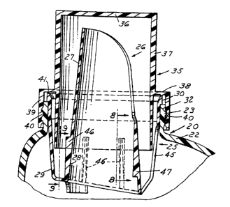
FIG. 1 is a sectional view of a liquid containing and
dispensing package embodying the invention.
FIG. 2 is a bottom plan view of the f itment in the
package.
FIG. 3 is a top plan view of the fitment.
FIG. 4 is a front elevational view of the fitment as
viewed from the right in FIG. 1.
FIG. 5 is a fragmentary sectional view taken along
the line 5-5 in FIG. 3.
FIG. 6 is an elevational view of the f itment as viewed
from the left in FIG. 1.
FIG. 7 is a fragmentary view on an enlarged scale of
the lower portion of the fitment shown in FIG. 5.
FIG. 8 is a fragmentary sectional view taken along
the line 8-8 in FIG. 1.
FIG. 9 is a fragmentary sectional view taken along
the line 9-9 in FIG. 1.
FIG. 10 is a fragmentary sectional view on an enlarged
scale of a portion of the upper edge of the fitment.
-4-

CA 02156462 2004-02-18 ~' '~
Description of the Preferred Embodiments
In accordance with the invention, the container
package 20 comprises a hollow plastic container having a
body 22 and a neck 32. The neck 32 ~is formed with external
threads 23 . The package 20 further includes a f itment or insert
25 that comprises a centrally disposed inner spout portion 26
that has an arcuate upper portion 27 which is generally C-shaped
in transverse cross-section. The spout 26 has an annular lower
portion 28. The fitment 25 further includes an outer wall
portion 29 interconnected by an annular portion and extending
generally upwardly and outwardly. The outer wall portion 29
further includes a peripheral flange 30 adapted to engage the
upper surface of the neck 32.
The package 20 further includes a.closure 35 that
is generally cylindrical including a top wall 36 and a peripheral
wall 37. The peripheral wall 37 extends downwardly within the
walls of the spout 26. The cap 35 further includes an annular
wall 38 extending radially outwardly intermediate the ends of
the peripheral wall 3? and an annular axial skirt 39 extending
downwardly and having internal threads 40 engaging the external
threads 23 on the neck 32.
The wall 38 of the closure includes an annular
downwardly extending annular projection in the form of a bead
41, preferably having a V cross-section, that engages the fitment
25 to provide a primary seal between the closure 35 and the
fitment 25 and, in turn, force the fitment 25 against the end'
of the neck 32.
-5-


CA 02156462 2004-02-18
The container may be made of plastic material such
as high density polyethylene. The fitment 25 may be made of
other plastic materials, for example, low density polyethylene.
The closure 35 may be made of plastic material such as
polypropylene.
The wall of the fitment is provided with an axially
extending opening or slot 45 that extends from a position aligned
with the junction of the C-shaped portion and annular portion
to define a combined drain back opening and near empty pour out
hole.
Unlike earlier pour spouts or fitments 25, where the
drain and near empty holes are separate, this spout or fitment
25 has one continuous, uninterrupted slot, which is a combination
of the earlier drain and near empty holes. By combining these
two individual features into one, the tooling used to manufacture
the spout is simplified, and the component is easier to produce
as well.
The drain back and near-empty holes remain separate,
but by including a chamfer or recess at the base of the near-
empty hole, the design will allow the tooling to also be
simplified, as there would be only positive taper surfaces in
the direction of draw.
Thefitment 25further includescircum~erential spaced
vertical ribs 46 on the outer surface of the lower portion 28
(FIGS. 5, 9) and a single vertical rib 47 on the inner surface
of the lower portion 28 opposite the opening 45.
-6-


y' The vertical ribs 46 facilitate stacking of the
fitments. First, after the parts are manufactured, they are
stacked one on top of the other, about twenty (20) high. These
stacks are then placed on their side in the shipping cartons,
and multiple stacks laid upon each other. This method of
packaging greatly improves the efficiency of the cartons. The
vertical rib 46 prevents the spouts in stacks from being
compressed too much. If the vertical ribs were not included
as shown, the parts which have multiple tapered surfaces, could
be stacked so tightly together, that the equipment used to pick
and place the spouts into the container would malfunction. The
function of the rib 47 is utilized with the machinery used to
place the spout.
In particular, the single, unsymmetrical rib 46 is
used for orienting the spout relative to the container, so that
the spout's front pouring edge is placed towards the front
cbntainer, opposite of the handle of the container.
It can thus be seen that there has been provided a
liquid dispensing package wherein the spout fitment or insert
has improved mold ability in larger size spouts; which inquires
less complicated tooling such that is easier to mold.

Dessin représentatif
Une figure unique qui représente un dessin illustrant l'invention.
États administratifs

Pour une meilleure compréhension de l'état de la demande ou brevet qui figure sur cette page, la rubrique Mise en garde , et les descriptions de Brevet , États administratifs , Taxes périodiques et Historique des paiements devraient être consultées.

États administratifs

Titre Date
Date de délivrance prévu 2004-11-23
(22) Dépôt 1995-08-18
(41) Mise à la disponibilité du public 1996-02-26
Requête d'examen 1999-09-29
(45) Délivré 2004-11-23
Réputé périmé 2014-08-19

Historique d'abandonnement

Il n'y a pas d'historique d'abandonnement

Historique des paiements

Type de taxes Anniversaire Échéance Montant payé Date payée
Le dépôt d'une demande de brevet 0,00 $ 1995-08-18
Enregistrement de documents 0,00 $ 1995-11-09
Taxe de maintien en état - Demande - nouvelle loi 2 1997-08-18 100,00 $ 1997-06-26
Taxe de maintien en état - Demande - nouvelle loi 3 1998-08-18 100,00 $ 1998-06-30
Taxe de maintien en état - Demande - nouvelle loi 4 1999-08-18 100,00 $ 1999-07-06
Requête d'examen 400,00 $ 1999-09-29
Taxe de maintien en état - Demande - nouvelle loi 5 2000-08-18 150,00 $ 2000-06-23
Taxe de maintien en état - Demande - nouvelle loi 6 2001-08-20 150,00 $ 2001-07-11
Taxe de maintien en état - Demande - nouvelle loi 7 2002-08-19 150,00 $ 2002-06-26
Taxe de maintien en état - Demande - nouvelle loi 8 2003-08-18 150,00 $ 2003-06-20
Taxe de maintien en état - Demande - nouvelle loi 9 2004-08-18 200,00 $ 2004-07-13
Taxe finale 300,00 $ 2004-09-03
Taxe de maintien en état - brevet - nouvelle loi 10 2005-08-18 250,00 $ 2005-07-08
Taxe de maintien en état - brevet - nouvelle loi 11 2006-08-18 250,00 $ 2006-07-07
Taxe de maintien en état - brevet - nouvelle loi 12 2007-08-20 250,00 $ 2007-07-04
Enregistrement de documents 100,00 $ 2008-06-10
Taxe de maintien en état - brevet - nouvelle loi 13 2008-08-18 250,00 $ 2008-07-15
Taxe de maintien en état - brevet - nouvelle loi 14 2009-08-18 250,00 $ 2009-07-13
Taxe de maintien en état - brevet - nouvelle loi 15 2010-08-18 450,00 $ 2010-07-15
Taxe de maintien en état - brevet - nouvelle loi 16 2011-08-18 450,00 $ 2011-08-01
Taxe de maintien en état - brevet - nouvelle loi 17 2012-08-20 450,00 $ 2012-07-30
Enregistrement de documents 100,00 $ 2014-05-26
Titulaires au dossier

Les titulaires actuels et antérieures au dossier sont affichés en ordre alphabétique.

Titulaires actuels au dossier
KUBETECH CUSTOM MOLDING, INC.
Titulaires antérieures au dossier
HAFFNER, EUGENE F.
OWENS-ILLINOIS CLOSURE INC.
REXAM CLOSURE SYSTEMS INC.
REXAM CONSUMER PLASTICS INC.
RIOS, LUZ
Les propriétaires antérieurs qui ne figurent pas dans la liste des « Propriétaires au dossier » apparaîtront dans d'autres documents au dossier.
Documents

Pour visionner les fichiers sélectionnés, entrer le code reCAPTCHA :


Pour visualiser une image, cliquer sur un lien dans la colonne description du document. Pour télécharger l'image (les images), cliquer l'une ou plusieurs cases à cocher dans la première colonne et ensuite cliquer sur le bouton "Télécharger sélection en format PDF (archive Zip)" ou le bouton "Télécharger sélection (en un fichier PDF fusionné)".

Liste des documents de brevet publiés et non publiés sur la BDBC .

Si vous avez des difficultés à accéder au contenu, veuillez communiquer avec le Centre de services à la clientèle au 1-866-997-1936, ou envoyer un courriel au Centre de service à la clientèle de l'OPIC.


Description du
Document 
Date
(yyyy-mm-dd) 
Nombre de pages   Taille de l'image (Ko) 
Dessins représentatifs 1998-04-23 1 21
Page couverture 2004-10-20 1 55
Revendications 1999-11-22 4 135
Page couverture 1996-04-17 1 16
Abrégé 1996-02-26 1 39
Description 1996-02-26 7 208
Revendications 1996-02-26 4 117
Dessins 1996-02-26 3 104
Description 2001-02-18 7 213
Dessins 2001-02-18 3 104
Revendications 2001-02-18 4 132
Dessins représentatifs 2004-03-24 1 14
Correspondance 2004-09-03 1 32
Cession 1995-08-18 6 264
Poursuite-Amendment 1999-09-29 1 38
Correspondance 1995-10-10 7 208
Poursuite-Amendment 1999-11-30 1 26
Poursuite-Amendment 2003-08-21 3 119
Poursuite-Amendment 2004-02-18 10 369
Cession 2008-06-10 6 170
Cession 2014-05-26 15 363