Language selection

Search

Patent 2161178 Summary

Third-party information liability

Some of the information on this Web page has been provided by external sources. The Government of Canada is not responsible for the accuracy, reliability or currency of the information supplied by external sources. Users wishing to rely upon this information should consult directly with the source of the information. Content provided by external sources is not subject to official languages, privacy and accessibility requirements.

Claims and Abstract availability

Any discrepancies in the text and image of the Claims and Abstract are due to differing posting times. Text of the Claims and Abstract are posted:

  • At the time the application is open to public inspection;
  • At the time of issue of the patent (grant).
(12) Patent: (11) CA 2161178
(54) English Title: A CABINET WALL BOARD ASSEMBLY
(54) French Title: PANNEAUX MURAUX POUR TRAVAUX D'EBENISTERIE
Status: Deemed expired
Bibliographic Data
(51) International Patent Classification (IPC):
  • A47B 96/14 (2006.01)
(72) Inventors :
  • LEE, SHANG-MING (Taiwan, Province of China)
(73) Owners :
  • LEE, SHANG-MING (Taiwan, Province of China)
(71) Applicants :
  • LEE, SHANG-MING (Taiwan, Province of China)
(74) Agent: FETHERSTONHAUGH & CO.
(74) Associate agent:
(45) Issued: 1999-09-07
(22) Filed Date: 1995-10-23
(41) Open to Public Inspection: 1997-04-24
Examination requested: 1995-10-23
Availability of licence: N/A
(25) Language of filing: English

Patent Cooperation Treaty (PCT): No

(30) Application Priority Data: None

Abstracts

English Abstract


A cabinet wall board assembly including a
horizontal board, a wall board and multiple adjoining
members. The horizontal board is formed with a
connecting channel and each adjoining member has a first
end for inserting into the connecting channel, a second
end disposed with multiple equally spaced tenons and an
engaging face under the tenons. Each tenon has an arch
bottom. The wall board has an upper end disposed with
multiple dovetail mortises corresponding to the tenons
of the adjoining member and has a supporting face on
inner side of the dovetail mortises for engaging with
the engaging face of the adjoining member. The
horizontal board is associated with the wall board with
the tenons inserted in the mortises and the engaging
face supported by the supporting face so that the
horizontal board is reinforced to bear heavier load. In
a working site, the horizontal board and the wall board
can be easily and quickly assembled into the cabinet.


Claims

Note: Claims are shown in the official language in which they were submitted.

-5-

WHAT IS CLAIMED IS:


1. A cabinet wall board assembly comprising:


a horizontal board formed with a connecting
channel;


multiple adjoining members each having a first end
for inserting into the connecting channel and a second
end disposed with multiple equally spaced tenons, each
tenon having an arch bottom, an end face and a root
portion, the tenon being tapered from the end face to
the root portion, each adjoining member further having
an engaging face under the tenons; and


a wall board having an upper end disposed with
multiple dovetail mortises corresponding to the tenons
of the adjoining member and having a supporting face on
inner side of the dovetail mortises for engaging with
the engaging face of the adjoining member.


Description

Note: Descriptions are shown in the official language in which they were submitted.


~161178


A CABINET WALL BOARD ASSEMBLY

BACKGROUND OF THE INVENTION

The present invention relates to a cabinet wall
board assembly, and more particularly to a cabinet wall
board assembly which can be directly assembled according
to the size of the board material and in which the load
on the horizontal board is fully supported by the
adjoining portions of the horizontal board and the wall
board.

The existing assembled cabinet is composed of
several wooden horizontal boards and wall boards which
are directly formed with tenons and mortises. Such
cabinet is assembled by means of engaging the tenons
with the mortises without using any nail. However,
during manufacturing, in case the board material has
relatively large area, a large work bench will be
necessary for the working. This causes difficulty and
inconveniency in working and affects the production
efficiency.

In addition, the tenons and mortises of the
2~ conventional assembled cabinet are designed with
cooperative rectangular shape which is often deformed by
humidity after a period of use. Under such circumstance,

~161178


it often takes place that the tenons are stuck in the
mortises when engaged therewith.


SUMMARY OF THE INVENTION


It is therefore a primary object of the present
invention to provide a cabinet wall board assembly which
can be directly assembled according to the size of the
board material and in which the horizontal board is

easily and quickly assembled with the wall board and the
load on the horizonal board is firmly supported thereby.


It is a further object of the present invention to
provide the above cabinet wall board assembly including
several separate ad30ining members, whereby the wall
board asse~bly can be freely adjustably assembled
according to the size of the board material and can be
mass-produced to reduce the manufacturing cost.


It is still a further object of the present
invention to provide the above cabinet wall board
assembly in which the tenons of the adjoining members
has arch bottoms so that when inserted into the
mortises, the tenons are easily guided thereinto.

The present invention can be best understood
through the following description and accompanying

c~ 7 ~
--3--

drawing, wherein:

BRIEF DESCRIPTION OF THE DRAWINGS

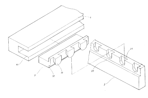
Fig. 1 is a perspective exploded view of the
present invention;
~ig. 2 is a perspective assembled view of the
present invention; and
Fig. 3 is a side sectional view of the present
invention.

DETAILED DESCRIPTION OF THE PREFERRED EMBODIMENT

Please refer to Fig. 1. The present invention
includes a horizontal board 1, a wall board 2 and
multiple adjoining members 3. The horizontal board 1 is
formed with a connecting channel 11 and the adjoining
member 3 has several equally spaced tenons 31 at front
end. Each tenon 31 has an arch bottom, an end face 311
and a root portion 312. The tenon 31 is tapered from the
end face 311 to the root portion 312 as shown in Fig. 3.
The wall board 2 has multiple dovetail mortises 21 at
upper end corresponding to the tenons 31 of the
adjoining member 3. Each mortise 21 has an arch bottom
as the arch bottom of the tenon 31. A supporting face 22
is formed on an inner side of the dovetail mortise 21 of
the wall board 2.

~1611 7~


Please refer to Fig. 2. The adjoining member 3 is
fitted in the connecting channel 11 of the horizontal
board 1. The number of the adjoining members 3 is
determined by the size of the horizontal board 1. By
means of the arch bottom of the tenon 31, when inserted
into the mortise 21 of the wall board 2, the tenon 31 is
guided into the mortise 21 without being stuck therein.
In addition, the adjoining member 3 has an engaging face
32 for engaging with the supporting face 22 of the wall
board 2 and the tenons 31 are snugly firmly fitted in
the mortises 21, whereby the horizontal board 1 is able
to fully bear both vertical and horizontal load.

Please refer to Fig. 3. When fitted with the
horizontal board 1, the adjoining member 3 can be
adjusted and slided forward or rearward within the
connecting channel 11 according to actual requirement so
as to tightly associate the horizontal board 1 with the
wall board 2.

It is to be understood that the above description
and drawings are only used for illustrating one
embodiment of the present invention, not intended to
limit the scope thereof. Any variation and derivation
from the above description and drawings should be
included in the scope of the present invention.

Representative Drawing
A single figure which represents the drawing illustrating the invention.
Administrative Status

For a clearer understanding of the status of the application/patent presented on this page, the site Disclaimer , as well as the definitions for Patent , Administrative Status , Maintenance Fee  and Payment History  should be consulted.

Administrative Status

Title Date
Forecasted Issue Date 1999-09-07
(22) Filed 1995-10-23
Examination Requested 1995-10-23
(41) Open to Public Inspection 1997-04-24
(45) Issued 1999-09-07
Deemed Expired 2007-10-23

Abandonment History

There is no abandonment history.

Payment History

Fee Type Anniversary Year Due Date Amount Paid Paid Date
Request for Examination $200.00 1995-10-23
Application Fee $0.00 1995-10-23
Maintenance Fee - Application - New Act 2 1997-10-23 $100.00 1997-07-30
Maintenance Fee - Application - New Act 3 1998-10-23 $100.00 1998-10-16
Final Fee $150.00 1999-06-02
Maintenance Fee - Patent - New Act 4 1999-10-25 $100.00 1999-10-13
Maintenance Fee - Patent - New Act 5 2000-10-23 $75.00 2000-10-17
Maintenance Fee - Patent - New Act 6 2001-10-23 $75.00 2001-08-24
Maintenance Fee - Patent - New Act 7 2002-10-23 $150.00 2002-10-15
Maintenance Fee - Patent - New Act 8 2003-10-23 $150.00 2003-10-22
Maintenance Fee - Patent - New Act 9 2004-10-25 $200.00 2004-10-14
Maintenance Fee - Patent - New Act 10 2005-10-24 $250.00 2005-09-28
Owners on Record

Note: Records showing the ownership history in alphabetical order.

Current Owners on Record
LEE, SHANG-MING
Past Owners on Record
None
Past Owners that do not appear in the "Owners on Record" listing will appear in other documentation within the application.
Documents

To view selected files, please enter reCAPTCHA code :


To view images, click a link in the Document Description column. To download the documents, select one or more checkboxes in the first column and then click the "Download Selected in PDF format (Zip Archive)" or the "Download Selected as Single PDF" button.

List of published and non-published patent-specific documents on the CPD .

If you have any difficulty accessing content, you can call the Client Service Centre at 1-866-997-1936 or send them an e-mail at CIPO Client Service Centre.


Document
Description 
Date
(yyyy-mm-dd) 
Number of pages   Size of Image (KB) 
Claims 1996-03-15 1 24
Abstract 1996-03-15 1 29
Cover Page 1996-03-15 1 14
Description 1996-03-15 4 128
Drawings 1996-03-15 3 36
Cover Page 1998-07-09 1 14
Cover Page 1999-08-31 1 42
Representative Drawing 1997-07-10 1 19
Representative Drawing 1999-08-31 1 12
Fees 2000-10-17 1 40
Fees 2003-10-22 1 36
Fees 2002-10-15 1 38
Correspondence 2001-08-24 1 35
Assignment 1995-10-23 3 119
Correspondence 1999-06-02 2 58