Language selection

Search

Patent 2163057 Summary

Third-party information liability

Some of the information on this Web page has been provided by external sources. The Government of Canada is not responsible for the accuracy, reliability or currency of the information supplied by external sources. Users wishing to rely upon this information should consult directly with the source of the information. Content provided by external sources is not subject to official languages, privacy and accessibility requirements.

Claims and Abstract availability

Any discrepancies in the text and image of the Claims and Abstract are due to differing posting times. Text of the Claims and Abstract are posted:

  • At the time the application is open to public inspection;
  • At the time of issue of the patent (grant).
(12) Patent Application: (11) CA 2163057
(54) English Title: AUXILIARY LOCK
(54) French Title: SERRURE AUXILIAIRE
Status: Dead
Bibliographic Data
(51) International Patent Classification (IPC):
  • E05B 57/00 (2006.01)
  • E05B 15/02 (2006.01)
  • E05B 17/20 (2006.01)
  • E05B 63/00 (2006.01)
  • E05B 63/08 (2006.01)
(72) Inventors :
  • ADELMEYER, GERARD G. (United States of America)
(73) Owners :
  • EMHART INC. (United States of America)
(71) Applicants :
  • EMHART INC. (United States of America)
(74) Agent: NORTON ROSE FULBRIGHT CANADA LLP/S.E.N.C.R.L., S.R.L.
(74) Associate agent:
(45) Issued:
(22) Filed Date: 1995-11-16
(41) Open to Public Inspection: 1996-06-08
Examination requested: 2000-01-24
Availability of licence: N/A
(25) Language of filing: English

Patent Cooperation Treaty (PCT): No

(30) Application Priority Data:
Application No. Country/Territory Date
08/350,599 United States of America 1994-12-07

Abstracts

English Abstract


An auxiliary lock comprising a latch assembly
having an elongated casing to be received by a first
horizontal bore extending into the end of the door,
a cylinder mechanism to be received by a second
horizontal thru bore extending, from one face of the
door to the other face of the door and intersecting
the first bore. The cylinder mechanism includes a
cylinder having a chimney, a cylindrical guard having
an annular door engaging surface, an annular lip
projecting inwardly from the annular door engaging
surface to be received by the second thru bore, a
cylindrical segment projecting inwardly from the
annular lip, a strut projecting radially upwardly
from one circumferential end of the segment and
defining therewith a shaped structure. The strut has
a length selected so that the shaped structure lies
proximate the bottom of said casing to thereby
prevent the rotation of said guard.


Claims

Note: Claims are shown in the official language in which they were submitted.


The embodiments of the invention in which an exclusive
property or privilege is claimed are defined as follows:
1. An auxiliary lock for a door having mutually
perpendicular latch and lockset holes comprising
a latch assembly having an elongated
casing to be received by the latch hole,
a cylinder lock assembly for insertion
into the lockset hole including
a cylinder housing having a chimney,
a cylindrical guard having
a front face having a housing
receiving opening for preventing relative rotation
therebetween,
an annular door engaging
surface,
an annular lip projecting
inwardly from said annular door engaging surface for
insertion into the lockset hole, and
a torque limiting structure
projecting inwardly for preventing the rotation of
said cylindrical guard in either direction, said
torque limiting structure occupying one quadrant of
the lockset hole.

2. An auxiliary lock according to claim 1, wherein
said torque limiting structure comprises
a cylindrical segment projecting inwardly
from said annular lip, the uppermost end of said
cylindrical segment lying beneath and proximate to
said casing, and
a strut projecting radially upwardly from
the other end of said cylindrical segment to a
location beneath and proximate to said casing.

3. An auxiliary lock according to claim 1, further
comprising a second identical cylinder lock assembly.


- 4 -


4. An auxiliary lock according to claim 2, wherein
said strut extends rearwardly beyond said annular
door engaging face.

5. An auxiliary lock according to claim 4, further
comprising a second identical cylindrical lock
assembly.

6. An auxiliary lock according to claim 4, wherein
said cylinder housing further comprises a barrel
portion and said strut underlies said barrel portion.


- 5 -

Description

Note: Descriptions are shown in the official language in which they were submitted.


2163057

SPECIFICATION
AUXILIARY LOCK

The present invention relates to auxiliary
locks, often referred to as deadbolts, and more
particularly to auxiliary locks having a torque
limiting feature.
Auxiliary locks conventionally have design
features for deterring illegal entries. For example,
cylinder guards are provided for enclosing the
locking cylinder housing. These guards may have an
annular lip extending into the door hole to restrict
access by screwdrivers and the like. Torque limiting
structures, which could interconnect to or be
integral with the guard, may also be provided which
will cooperate with the latch casing for preventing
rotation of the guard which could break the mounting
screws.
U.S. patent no. 4,338,804 discloses a single
cylinder auxiliary lock having a circumferential
shield which usually has a pair of opposed cutouts
(two cutouts will make the shield reversible and
capable of cooperating with a long latch assembly
casing). This shield combines the desired annular
lip and torque limiting features. In the '804 patent
the shield and the cylinder guard are separate parts
but in a cast unit these two parts could be part of
the exterior guard.
It is an object of the present invention to
provide a universal cast exterior/interior guard
having an annular lip and a torque limiting feature
so that a single cylinder auxiliary lock can be
assembled using one cast guard and a double cylinder
auxiliary lock can be assembled using two of these
identical guards.
It is also an object of the present invention
to provide a universal cast exterior/interior guard
that can be used as the interior and exterior guard
with doors having a thickness which varies between

2163057

predefined limits (1~8ll to 1~," for example).
Other objects and advantages of the present
invention will become apparent from the following
portion of this specification and from the accompany-
ing drawings which illustrate in accordance with themandate of the patent statutes a presently preferred
embodiment incorporating the principles of the
invention.
Referring to the drawings:
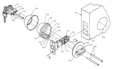
Figure 1 is an oblique separated view showing
a single cylinder deadbolt incorporating the
teachings of the present invention;
Figure 2 is a view taken at 2-2 of Figure l;
Figure 3 is a top view showing how first and
second cylinder guards would appear on a door of
minimum thickness with the guard cover and cylinder
housing for each guard separated; and
Figure 4 is a view taken at 2-2 of Figure 1 but
showing a double cylinder configuration.
A single cylinder auxiliary lock is shown in
Figure 1. On the exterior side of a door 8 is
located a cylinder housing portion 10 of a cylinder
assembly which includes a chimney 12 (the location of
the locking pins) and an axially extending torque
blade 14 which enters a suitable thru hole 16 in the
casing 18 of the latch assembly 20 which is received
in a latch hole 21 in the door.
To secure the auxiliary lock to the door, a
pair of mounting screws 22 extend through holes 24 in
an interior turn piece and rose assembly 26, through
holes 27 in the latch assembly 20, and are received
by threaded holes 28 in the cylinder housing portion
10. To protect the cylinder housing portion 10, a
cylinder guard 30 is provided which is dressed with
a cover 32. The cylinder guard has an annular flat
door engaging surface 40 which will be forced into
engagement with the door during assembly and a

2163057


cylindrical or annular lip 42 which has a diameter
selected so that it will fit into the lockset hole 43
in the door 8. Opposed cutouts 44 are provided on
the annular lip to accommodate the latch casing 18.
Referring to Figure 2, the opening in the front face
of the guard includes a slot 45 to receive or capture
the chimney 12 of the associated cylinder housing
thereby properly orienting the cylinder guard and
preventing relative rotation.
Projecting into the door and beneath the casing
18 is a shaped tongue 50 which occupies one quadrant
of the lockset hole and which is defined by a cylind-
rical inwardly extending segment 52 which is a
continuation of the annular lip 42 and a radial strut
54 which projects vertically upwardly from the lower
edge of the segment and continues rearwardly to the
front of the cylinder guard. As can be seen from
Figure 2, the top 55 of the radial strut 54 and the
top end 53 of the cylindrical segment 52 end beneath
and proximate to the latch casing thereby preventing
rotation of the cylinder guard 30 in either direc-
tion. The strut extends toward the exterior end of
the housing 10 to provide support for housing barrel
60 and has a slight rib 57 to strengthen the
structure.
In the double lock configuration (Figures 3 and
4), the turn piece and rose assembly 26 is replaced
by a second cylinder housing 110, guard 130 and cover
132. Since the door may vary in thickness, the
torque limiting tongues 50, 150 of the cylinder
guards can lie side by side beneath the latch
assembly casing with the tops 53, 153 of the circular
segments 52, 152 and the tops 55, 155 of the radial
struts 54, 154 proximate the latch assembly casing
18.

C:\WP51\SCD\478703US.SPC
Representative Drawing
A single figure which represents the drawing illustrating the invention.
Administrative Status

For a clearer understanding of the status of the application/patent presented on this page, the site Disclaimer , as well as the definitions for Patent , Administrative Status , Maintenance Fee  and Payment History  should be consulted.

Administrative Status

Title Date
Forecasted Issue Date Unavailable
(22) Filed 1995-11-16
(41) Open to Public Inspection 1996-06-08
Examination Requested 2000-01-24
Dead Application 2003-11-17

Abandonment History

Abandonment Date Reason Reinstatement Date
2002-11-18 FAILURE TO PAY APPLICATION MAINTENANCE FEE
2002-12-19 FAILURE TO PAY FINAL FEE

Payment History

Fee Type Anniversary Year Due Date Amount Paid Paid Date
Application Fee $0.00 1995-11-16
Registration of a document - section 124 $0.00 1996-02-08
Maintenance Fee - Application - New Act 2 1997-11-17 $100.00 1997-10-29
Maintenance Fee - Application - New Act 3 1998-11-16 $100.00 1998-11-02
Maintenance Fee - Application - New Act 4 1999-11-16 $100.00 1999-11-04
Request for Examination $400.00 2000-01-24
Maintenance Fee - Application - New Act 5 2000-11-16 $150.00 2000-11-03
Maintenance Fee - Application - New Act 6 2001-11-16 $150.00 2001-11-13
Owners on Record

Note: Records showing the ownership history in alphabetical order.

Current Owners on Record
EMHART INC.
Past Owners on Record
ADELMEYER, GERARD G.
Past Owners that do not appear in the "Owners on Record" listing will appear in other documentation within the application.
Documents

To view selected files, please enter reCAPTCHA code :


To view images, click a link in the Document Description column. To download the documents, select one or more checkboxes in the first column and then click the "Download Selected in PDF format (Zip Archive)" or the "Download Selected as Single PDF" button.

List of published and non-published patent-specific documents on the CPD .

If you have any difficulty accessing content, you can call the Client Service Centre at 1-866-997-1936 or send them an e-mail at CIPO Client Service Centre.


Document
Description 
Date
(yyyy-mm-dd) 
Number of pages   Size of Image (KB) 
Representative Drawing 1999-08-09 1 25
Representative Drawing 2002-06-12 1 16
Description 2000-03-21 4 168
Claims 2000-03-21 2 45
Cover Page 1997-04-02 1 15
Abstract 1996-06-08 1 26
Description 1996-06-08 3 137
Claims 1996-06-08 2 49
Drawings 1996-06-08 3 73
Assignment 1995-11-16 8 246
Prosecution-Amendment 2000-01-24 9 364
Prosecution-Amendment 2000-03-21 6 168