Sélection de la langue

Search

Sommaire du brevet 2163057 

Énoncé de désistement de responsabilité concernant l'information provenant de tiers

Une partie des informations de ce site Web a été fournie par des sources externes. Le gouvernement du Canada n'assume aucune responsabilité concernant la précision, l'actualité ou la fiabilité des informations fournies par les sources externes. Les utilisateurs qui désirent employer cette information devraient consulter directement la source des informations. Le contenu fourni par les sources externes n'est pas assujetti aux exigences sur les langues officielles, la protection des renseignements personnels et l'accessibilité.

Disponibilité de l'Abrégé et des Revendications

L'apparition de différences dans le texte et l'image des Revendications et de l'Abrégé dépend du moment auquel le document est publié. Les textes des Revendications et de l'Abrégé sont affichés :

  • lorsque la demande peut être examinée par le public;
  • lorsque le brevet est émis (délivrance).
(12) Demande de brevet: (11) CA 2163057
(54) Titre français: SERRURE AUXILIAIRE
(54) Titre anglais: AUXILIARY LOCK
Statut: Morte
Données bibliographiques
(51) Classification internationale des brevets (CIB):
  • E05B 57/00 (2006.01)
  • E05B 15/02 (2006.01)
  • E05B 17/20 (2006.01)
  • E05B 63/00 (2006.01)
  • E05B 63/08 (2006.01)
(72) Inventeurs :
  • ADELMEYER, GERARD G. (Etats-Unis d'Amérique)
(73) Titulaires :
  • EMHART INC. (Etats-Unis d'Amérique)
(71) Demandeurs :
  • EMHART INC. (Etats-Unis d'Amérique)
(74) Agent: NORTON ROSE FULBRIGHT CANADA LLP/S.E.N.C.R.L., S.R.L.
(74) Co-agent:
(45) Délivré:
(22) Date de dépôt: 1995-11-16
(41) Mise à la disponibilité du public: 1996-06-08
Requête d'examen: 2000-01-24
Licence disponible: S.O.
(25) Langue des documents déposés: Anglais

Traité de coopération en matière de brevets (PCT): Non

(30) Données de priorité de la demande:
Numéro de la demande Pays / territoire Date
08/350,599 Etats-Unis d'Amérique 1994-12-07

Abrégés

Abrégé anglais


An auxiliary lock comprising a latch assembly
having an elongated casing to be received by a first
horizontal bore extending into the end of the door,
a cylinder mechanism to be received by a second
horizontal thru bore extending, from one face of the
door to the other face of the door and intersecting
the first bore. The cylinder mechanism includes a
cylinder having a chimney, a cylindrical guard having
an annular door engaging surface, an annular lip
projecting inwardly from the annular door engaging
surface to be received by the second thru bore, a
cylindrical segment projecting inwardly from the
annular lip, a strut projecting radially upwardly
from one circumferential end of the segment and
defining therewith a shaped structure. The strut has
a length selected so that the shaped structure lies
proximate the bottom of said casing to thereby
prevent the rotation of said guard.

Revendications

Note : Les revendications sont présentées dans la langue officielle dans laquelle elles ont été soumises.


The embodiments of the invention in which an exclusive
property or privilege is claimed are defined as follows:
1. An auxiliary lock for a door having mutually
perpendicular latch and lockset holes comprising
a latch assembly having an elongated
casing to be received by the latch hole,
a cylinder lock assembly for insertion
into the lockset hole including
a cylinder housing having a chimney,
a cylindrical guard having
a front face having a housing
receiving opening for preventing relative rotation
therebetween,
an annular door engaging
surface,
an annular lip projecting
inwardly from said annular door engaging surface for
insertion into the lockset hole, and
a torque limiting structure
projecting inwardly for preventing the rotation of
said cylindrical guard in either direction, said
torque limiting structure occupying one quadrant of
the lockset hole.

2. An auxiliary lock according to claim 1, wherein
said torque limiting structure comprises
a cylindrical segment projecting inwardly
from said annular lip, the uppermost end of said
cylindrical segment lying beneath and proximate to
said casing, and
a strut projecting radially upwardly from
the other end of said cylindrical segment to a
location beneath and proximate to said casing.

3. An auxiliary lock according to claim 1, further
comprising a second identical cylinder lock assembly.


- 4 -


4. An auxiliary lock according to claim 2, wherein
said strut extends rearwardly beyond said annular
door engaging face.

5. An auxiliary lock according to claim 4, further
comprising a second identical cylindrical lock
assembly.

6. An auxiliary lock according to claim 4, wherein
said cylinder housing further comprises a barrel
portion and said strut underlies said barrel portion.


- 5 -

Description

Note : Les descriptions sont présentées dans la langue officielle dans laquelle elles ont été soumises.


2163057

SPECIFICATION
AUXILIARY LOCK

The present invention relates to auxiliary
locks, often referred to as deadbolts, and more
particularly to auxiliary locks having a torque
limiting feature.
Auxiliary locks conventionally have design
features for deterring illegal entries. For example,
cylinder guards are provided for enclosing the
locking cylinder housing. These guards may have an
annular lip extending into the door hole to restrict
access by screwdrivers and the like. Torque limiting
structures, which could interconnect to or be
integral with the guard, may also be provided which
will cooperate with the latch casing for preventing
rotation of the guard which could break the mounting
screws.
U.S. patent no. 4,338,804 discloses a single
cylinder auxiliary lock having a circumferential
shield which usually has a pair of opposed cutouts
(two cutouts will make the shield reversible and
capable of cooperating with a long latch assembly
casing). This shield combines the desired annular
lip and torque limiting features. In the '804 patent
the shield and the cylinder guard are separate parts
but in a cast unit these two parts could be part of
the exterior guard.
It is an object of the present invention to
provide a universal cast exterior/interior guard
having an annular lip and a torque limiting feature
so that a single cylinder auxiliary lock can be
assembled using one cast guard and a double cylinder
auxiliary lock can be assembled using two of these
identical guards.
It is also an object of the present invention
to provide a universal cast exterior/interior guard
that can be used as the interior and exterior guard
with doors having a thickness which varies between

2163057

predefined limits (1~8ll to 1~," for example).
Other objects and advantages of the present
invention will become apparent from the following
portion of this specification and from the accompany-
ing drawings which illustrate in accordance with themandate of the patent statutes a presently preferred
embodiment incorporating the principles of the
invention.
Referring to the drawings:
Figure 1 is an oblique separated view showing
a single cylinder deadbolt incorporating the
teachings of the present invention;
Figure 2 is a view taken at 2-2 of Figure l;
Figure 3 is a top view showing how first and
second cylinder guards would appear on a door of
minimum thickness with the guard cover and cylinder
housing for each guard separated; and
Figure 4 is a view taken at 2-2 of Figure 1 but
showing a double cylinder configuration.
A single cylinder auxiliary lock is shown in
Figure 1. On the exterior side of a door 8 is
located a cylinder housing portion 10 of a cylinder
assembly which includes a chimney 12 (the location of
the locking pins) and an axially extending torque
blade 14 which enters a suitable thru hole 16 in the
casing 18 of the latch assembly 20 which is received
in a latch hole 21 in the door.
To secure the auxiliary lock to the door, a
pair of mounting screws 22 extend through holes 24 in
an interior turn piece and rose assembly 26, through
holes 27 in the latch assembly 20, and are received
by threaded holes 28 in the cylinder housing portion
10. To protect the cylinder housing portion 10, a
cylinder guard 30 is provided which is dressed with
a cover 32. The cylinder guard has an annular flat
door engaging surface 40 which will be forced into
engagement with the door during assembly and a

2163057


cylindrical or annular lip 42 which has a diameter
selected so that it will fit into the lockset hole 43
in the door 8. Opposed cutouts 44 are provided on
the annular lip to accommodate the latch casing 18.
Referring to Figure 2, the opening in the front face
of the guard includes a slot 45 to receive or capture
the chimney 12 of the associated cylinder housing
thereby properly orienting the cylinder guard and
preventing relative rotation.
Projecting into the door and beneath the casing
18 is a shaped tongue 50 which occupies one quadrant
of the lockset hole and which is defined by a cylind-
rical inwardly extending segment 52 which is a
continuation of the annular lip 42 and a radial strut
54 which projects vertically upwardly from the lower
edge of the segment and continues rearwardly to the
front of the cylinder guard. As can be seen from
Figure 2, the top 55 of the radial strut 54 and the
top end 53 of the cylindrical segment 52 end beneath
and proximate to the latch casing thereby preventing
rotation of the cylinder guard 30 in either direc-
tion. The strut extends toward the exterior end of
the housing 10 to provide support for housing barrel
60 and has a slight rib 57 to strengthen the
structure.
In the double lock configuration (Figures 3 and
4), the turn piece and rose assembly 26 is replaced
by a second cylinder housing 110, guard 130 and cover
132. Since the door may vary in thickness, the
torque limiting tongues 50, 150 of the cylinder
guards can lie side by side beneath the latch
assembly casing with the tops 53, 153 of the circular
segments 52, 152 and the tops 55, 155 of the radial
struts 54, 154 proximate the latch assembly casing
18.

C:\WP51\SCD\478703US.SPC
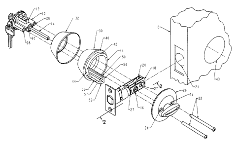
Dessin représentatif
Une figure unique qui représente un dessin illustrant l'invention.
États administratifs

Pour une meilleure compréhension de l'état de la demande ou brevet qui figure sur cette page, la rubrique Mise en garde , et les descriptions de Brevet , États administratifs , Taxes périodiques et Historique des paiements devraient être consultées.

États administratifs

Titre Date
Date de délivrance prévu Non disponible
(22) Dépôt 1995-11-16
(41) Mise à la disponibilité du public 1996-06-08
Requête d'examen 2000-01-24
Demande morte 2003-11-17

Historique d'abandonnement

Date d'abandonnement Raison Reinstatement Date
2002-11-18 Taxe périodique sur la demande impayée
2002-12-19 Taxe finale impayée

Historique des paiements

Type de taxes Anniversaire Échéance Montant payé Date payée
Le dépôt d'une demande de brevet 0,00 $ 1995-11-16
Enregistrement de documents 0,00 $ 1996-02-08
Taxe de maintien en état - Demande - nouvelle loi 2 1997-11-17 100,00 $ 1997-10-29
Taxe de maintien en état - Demande - nouvelle loi 3 1998-11-16 100,00 $ 1998-11-02
Taxe de maintien en état - Demande - nouvelle loi 4 1999-11-16 100,00 $ 1999-11-04
Requête d'examen 400,00 $ 2000-01-24
Taxe de maintien en état - Demande - nouvelle loi 5 2000-11-16 150,00 $ 2000-11-03
Taxe de maintien en état - Demande - nouvelle loi 6 2001-11-16 150,00 $ 2001-11-13
Titulaires au dossier

Les titulaires actuels et antérieures au dossier sont affichés en ordre alphabétique.

Titulaires actuels au dossier
EMHART INC.
Titulaires antérieures au dossier
ADELMEYER, GERARD G.
Les propriétaires antérieurs qui ne figurent pas dans la liste des « Propriétaires au dossier » apparaîtront dans d'autres documents au dossier.
Documents

Pour visionner les fichiers sélectionnés, entrer le code reCAPTCHA :


Pour visualiser une image, cliquer sur un lien dans la colonne description du document. Pour télécharger l'image (les images), cliquer l'une ou plusieurs cases à cocher dans la première colonne et ensuite cliquer sur le bouton "Télécharger sélection en format PDF (archive Zip)" ou le bouton "Télécharger sélection (en un fichier PDF fusionné)".

Liste des documents de brevet publiés et non publiés sur la BDBC .

Si vous avez des difficultés à accéder au contenu, veuillez communiquer avec le Centre de services à la clientèle au 1-866-997-1936, ou envoyer un courriel au Centre de service à la clientèle de l'OPIC.


Description du
Document 
Date
(yyyy-mm-dd) 
Nombre de pages   Taille de l'image (Ko) 
Dessins représentatifs 1999-08-09 1 25
Dessins représentatifs 2002-06-12 1 16
Description 2000-03-21 4 168
Revendications 2000-03-21 2 45
Page couverture 1997-04-02 1 15
Abrégé 1996-06-08 1 26
Description 1996-06-08 3 137
Revendications 1996-06-08 2 49
Dessins 1996-06-08 3 73
Cession 1995-11-16 8 246
Poursuite-Amendment 2000-01-24 9 364
Poursuite-Amendment 2000-03-21 6 168