Note: Descriptions are shown in the official language in which they were submitted.
2168172
Process for Fabricating Multisegment
Ridge Waveguides
The present invention relates to a process as set
forth in the preamble of claim 1.
With such a process, segmented optical waveguides can
be fabricated whose segments can be electrically
controlled or interrogated for their state via
separate metallic contacts.
The segments of such optical waveguides can be
operated and used, e.g., in optical communications, as
lasers, optical amplifiers, optical modulators,
absorbers, wavelength converters, or as passive
components, which do not provide light amplification.
Since the dimensions of such components are very
small, utmost precision is required during their
fabrication. Holding tolerances in the ~m range is so
complicated that alignment-changing processing steps,
such as further alignment or masking steps or
processing-tool changing during fabrication, cannot be
introduced without increasing the fabrication costs to
a prohibitive level. It is therefore desirable to find
a process in which no changes in tool geometry are
necessary during fabrication and in which as many
processing steps as possible are self-aligning steps.
This is the object of the invention. It is attained by
the process set forth in claim 1.
2 1 68 1 72
With the process according to the invention, laterally
very small structures (in the ~m range) can be formed
without the need for a special etching step
to separate the metallization between
adjoining segments. This, like the etching of the
ridge waveguide, is done in a self-aligning process
step (lift-off technique). This eliminates the need
for masking steps, which would require high alignment
accuracy and thus entail great expense.
A further development of the process according to the
invention is claimed in claim 2.
The process according to the invention will now be
described in detail with reference to the accompanying
drawings, in which:
ig. 1 shows a semiconductor layer structure on
a substrate, and
igs. 2 to 5 show the layer structure and the
formation of the optical waveguide by
the first, second, third, and last
process steps.
Fig. 1 shows a conventional semiconductor layer
structure which can serve as starting material for the
fabrication of active and passive optical waveguides.
On a substrate S, e.g., an InP layer, further
semiconductor layers have been grown, including a
group of layers AS, which comprises an active layer,
for example, over which a further InP layer InP and
finally a top layer DS of, e.g., heavily doped InGaAs
are provided, the top layer DS being only
2168172
approximately 0.3~m thick and etchable by a wet
chemical process.
If a segmented optical ridge waveguide with separate
metal contacts on the individual segments is to be
formed on a semiconductor chip containing the layer
structure of Fig. 1, the top layer i8 removed on both
sides of segment transition areas. This can be done by
dry etching, for example.
Fig. 2 shows a semiconductor chip - illustrated only
as a group of layers SP with the overlying top layer
DS to simplify the illustration - whose top layer has
two slots, SCH, on both sides of an area which will
later form a segment transition area ST.
Fig. 3 shows the same semiconductor chip with a
contact metallization KM deposited thereon. Here a
metal stripe only few ~ wide was formed on the chip
surface, disregarding the slots in the top layer. The
figure clearly shows that in the area of the slot
walls, the metallization is interrupted or at least
clearly reduced in thickness.
The contact metallization can be formed in any
conventional manner, such as by depositing a
photoresist layer which is exposed through a shadow
mask covering the area of the contact metallization,
then developed, coated with metal by a vapor
deposition process, and finally stripped, with the
metal on the top layer being not removed in the area
of the stripe covered by the shadow mask.
2168172
Fig. 4 shows the semiconductor chip after a ridge
structure R has been etched out below the contact
metallization by a dry chemical etching process, such
as RIE, IBE, or RIBE. In such processes, the metal
coating can serve as a mask, thus eliminating the need
for a special masking step.
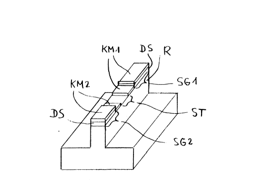
Fig. 5 shows the semiconductor chip with metal
contacts KMl, KM2 which are electrically separated
from each other. The separated contacts divide the
ridge waveguide R into two individually controllable
segments SG1, SG2. The segment transition area no
longer contains a metallization. This was achieved in
two steps. First, the entire chip except the segment
transition area was covered with photoresist in the
same way as described in connection with Fig. 3 for
the area of the contact metallization. Then, the top
layer still present in the segment transition area was
etched away by a wet chemical process, the
metallization in the segment transition area being
removed by undercutting.