Some of the information on this Web page has been provided by external sources. The Government of Canada is not responsible for the accuracy, reliability or currency of the information supplied by external sources. Users wishing to rely upon this information should consult directly with the source of the information. Content provided by external sources is not subject to official languages, privacy and accessibility requirements.
Any discrepancies in the text and image of the Claims and Abstract are due to differing posting times. Text of the Claims and Abstract are posted:
| (12) Patent Application: | (11) CA 2173386 |
|---|---|
| (54) English Title: | PANELS FOR THE MANUFACTURE OF CIRCULAR ABOVE-GROUND TANKS, MOULD, AND ASSOCIATED MANUFACTURING METHOD |
| (54) French Title: | PANNEAUX EN BETON ARME POUR L'OBTENTION DE RESERVOIRS CYLINDRIQUES HORS SOL ETC.; LE PROCEDE DE FABRICATION CORRESPONDANT |
| Status: | Deemed Abandoned and Beyond the Period of Reinstatement - Pending Response to Notice of Disregarded Communication |
| (51) International Patent Classification (IPC): |
|
|---|---|
| (72) Inventors : |
|
| (73) Owners : |
|
| (71) Applicants : |
|
| (74) Agent: | ROBIC AGENCE PI S.E.C./ROBIC IP AGENCY LP |
| (74) Associate agent: | |
| (45) Issued: | |
| (22) Filed Date: | 1996-04-03 |
| (41) Open to Public Inspection: | 1997-10-04 |
| Availability of licence: | N/A |
| Dedicated to the Public: | N/A |
| (25) Language of filing: | English |
| Patent Cooperation Treaty (PCT): | No |
|---|
| (30) Application Priority Data: | None |
|---|
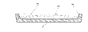
Reinforced concrete panel for the manufacture of
aboveground circular tanks, of the type comprising a
wall (1) fitted with a number of horizontal stiffening
ribs (3) which contain holes for the passage of
pre-stressing cables, wherein the said wall is flat and the
said holes are arc-shaped, and a method of manufacture
of said panels comprising the following stages:
- insertion of a flexible tubular element (11), of the
same length as an arc which presents a radius equal to
the radius of the tank and a chord equal to the width
of the panel, into a mould with mobile sides (8, 9), on
a pair of pegs (10) fitted to the sides at the
horizontal ribs of the panel; approach of the mobile
sides until the mould closes, so that the said flexible
tubular element takes on the arc shape required;
installation of reinforcement and laying of concrete;
concrete shaving; curing and removal of finished
product.
Panneau en béton armé pour la fabrication de réservoirs circulaires hors sol, de type comprenant une paroi (1) munie d'un certain nombre de raidisseurs horizontaux (3) dans lesquels ont été ménagés des trous pour le passage de câbles de précontrainte, ladite paroi étant plate et lesdits trous étant en forme d'arc. Est également l'objet de l'invention une méthode de fabrication desdits panneaux comprenant les étapes ci-après : insertion d'un élément tubulaire flexible (11) de la même longueur qu'un arc de rayon égal au rayon du réservoir, et de corde égale à la largeur du panneau, dans un moule avec parois mobiles (8, 9), sur une paire de piquets (10) fixés sur les côtés des nervures horizontales du panneau; approche des parois mobiles jusqu'à ce que le moule soit fermé, de sorte que ledit élément tubulaire flexible prenne la forme arquée requise; installation de l'armature et coulage du béton, arasage du béton, cure et enlèvement du produit fini
Note: Claims are shown in the official language in which they were submitted.
Note: Descriptions are shown in the official language in which they were submitted.
2024-08-01:As part of the Next Generation Patents (NGP) transition, the Canadian Patents Database (CPD) now contains a more detailed Event History, which replicates the Event Log of our new back-office solution.
Please note that "Inactive:" events refers to events no longer in use in our new back-office solution.
For a clearer understanding of the status of the application/patent presented on this page, the site Disclaimer , as well as the definitions for Patent , Event History , Maintenance Fee and Payment History should be consulted.
| Description | Date |
|---|---|
| Inactive: IPC deactivated | 2020-02-15 |
| Inactive: IPC assigned | 2019-06-04 |
| Inactive: IPC expired | 2019-01-01 |
| Inactive: IPC from MCD | 2006-03-12 |
| Inactive: IPC from MCD | 2006-03-12 |
| Inactive: IPC from MCD | 2006-03-12 |
| Time Limit for Reversal Expired | 2004-04-05 |
| Application Not Reinstated by Deadline | 2004-04-05 |
| Deemed Abandoned - Failure to Respond to Maintenance Fee Notice | 2003-04-03 |
| Inactive: Abandon-RFE+Late fee unpaid-Correspondence sent | 2003-04-03 |
| Inactive: Cover page published | 2000-12-21 |
| Application Published (Open to Public Inspection) | 1997-10-04 |
| Abandonment Date | Reason | Reinstatement Date |
|---|---|---|
| 2003-04-03 |
The last payment was received on 2002-02-08
Note : If the full payment has not been received on or before the date indicated, a further fee may be required which may be one of the following
Patent fees are adjusted on the 1st of January every year. The amounts above are the current amounts if received by December 31 of the current year.
Please refer to the CIPO
Patent Fees
web page to see all current fee amounts.
| Fee Type | Anniversary Year | Due Date | Paid Date |
|---|---|---|---|
| MF (application, 2nd anniv.) - standard | 02 | 1998-04-03 | 1998-02-06 |
| MF (application, 3rd anniv.) - standard | 03 | 1999-04-06 | 1999-03-23 |
| MF (application, 4th anniv.) - standard | 04 | 2000-04-03 | 2000-03-15 |
| MF (application, 5th anniv.) - standard | 05 | 2001-04-03 | 2001-03-12 |
| MF (application, 6th anniv.) - standard | 06 | 2002-04-03 | 2002-02-08 |
Note: Records showing the ownership history in alphabetical order.
| Current Owners on Record |
|---|
| GIUSEPPE PARENTI |
| Past Owners on Record |
|---|
| None |

