Language selection

Search

Patent 2181492 Summary

Third-party information liability

Some of the information on this Web page has been provided by external sources. The Government of Canada is not responsible for the accuracy, reliability or currency of the information supplied by external sources. Users wishing to rely upon this information should consult directly with the source of the information. Content provided by external sources is not subject to official languages, privacy and accessibility requirements.

Claims and Abstract availability

Any discrepancies in the text and image of the Claims and Abstract are due to differing posting times. Text of the Claims and Abstract are posted:

  • At the time the application is open to public inspection;
  • At the time of issue of the patent (grant).
(12) Patent Application: (11) CA 2181492
(54) English Title: IMPROVED CART
(54) French Title: VOITURETTE
Status: Dead
Bibliographic Data
(51) International Patent Classification (IPC):
  • B62B 3/12 (2006.01)
  • B62B 1/18 (2006.01)
(72) Inventors :
  • SORENSEN, TRAVIS WILLIAM (Canada)
(73) Owners :
  • SORENSEN, TRAVIS WILLIAM (Canada)
(71) Applicants :
  • SORENSEN, TRAVIS WILLIAM (Canada)
(74) Agent: R. WILLIAM WRAY & ASSOCIATES
(74) Associate agent:
(45) Issued:
(22) Filed Date: 1996-07-18
(41) Open to Public Inspection: 1998-01-19
Examination requested: 1997-04-10
Availability of licence: N/A
(25) Language of filing: English

Patent Cooperation Treaty (PCT): No

(30) Application Priority Data: None

Abstracts

English Abstract


There is described a combined wheelbarrow and cart
apparatus which provides a receptacle having a pair of
opposing side walls, a normally open front end, a bottom
wall having a front edge adjacent the front end, and a
transverse rear wall joining the side and bottom walls.
The bottom wall is bevelled for a short distance from the
front edge, and a longitudinal handle member extends
rearwardly from each side wall. A removable handle
crosspiece extends between the handle members and a wheel
is supported on each side of the apparatus.


Claims

Note: Claims are shown in the official language in which they were submitted.


- 4 -
The embodiments of the invention in which an exclusive
property or privilege is claimed are defined as follows:-

1. A combined wheelbarrow and cart apparatus
comprising in combination:
a receptacle having a pair of opposing side walls,
a normally open front end, a bottom wall having a front
edge adjacent said front end, and a transverse rear wall
joining said side and bottom walls,
the bottom wall being bevelled for a short distance
from said front edge,
a longitudinal handle member extending rearwardly
from each said side wall,
a removable handle crosspiece extending between the
handle members and
a wheel supported on each side of the apparatus.
2. Apparatus according to claim 1 wherein the wheels
are at opposite ends of a common axle.
3. Apparatus according to claim 1 wherein a mounting
bracket is attached to the exterior of each said side
wall, and each wheel is mounted on a wheel hub attached to
a respective mounting bracket to facilitate adjustment of
the wheel hub between different vertical positions.
4. Apparatus according to claim 1 including a fork
arrangement on either side of said apparatus for
supporting a wheel.
5. Apparatus according to claim 1, 2, 3 or 4 including
a further wheel of smaller diameter mounted approximately
centrally of the junction of said bottom wall and said
rear-wall and extending downwardly.
6. Apparatus according to claim 1, 2, 3 or 4 including
a downwardly extending foot member at the rear corner
junction of said bottom wall, rear wall and the respective
side wall.
7. Apparatus according to claim 1, 2, 3 or 4 including
a removable front wall.

- 5 -

8. Each and every novel feature or novel
combination of features herein disclosed.

Description

Note: Descriptions are shown in the official language in which they were submitted.


- 1 2 1 8 1 4 9~
The present invention relates to multipurpose
carrying apparatus.
Multipurpose carrying apparatus has previously been
proposed but manual operation is sometimes difficult.
It is an object of the invention to provide an
improved multipurpose carrying apparatus which has
increased versatility and can be used as a wheelbarrow or
as a cart.
According to the present invention there is
provided a combined wheelbarrow and cart apparatus
comprising in combination a receptacle having a pair of
opposing side walls, a normally open front end, a bottom
wall having a front edge adjacent said front end, and a
transverse rear wall joining said side and bottom walls,
the bottom wall being bevelled for a short distance from
said f ront edge, a longitudinal handle member PYtPnrl; n~
rearwardly from each said side wall, a removable handle
crosspiece extending between the handle members and a
wheel supported on each side of the apparatus.
~ orl;r--nts of the invention will now be described,
by way of example, with reference to the accompanying
drawings in which:-
Figure 1 is a di~grammatic representation ofmultipurpose apparatus according to one embodiment of the
invention,
Figure 2 is a diagrammatic representation according
to a second embodiment of the invention,
Figure 3 is a diagrammatic representation of
another embodiment with a different wheel support
a rrangement,
Figure 4 is a diagrammatic representation with yet
another wheel support arrangement, and
Figure 5 is a diagrammatic representation of a
further embodiment.

218~2
-- 2 --
The same reference numerals are applied to like
parts throughout.
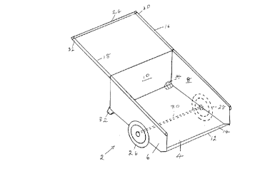
Referring to Figure 1 a wheelbarrow 2 is provided
with a bottom wall 4, two opposing side walls 6 and 8 and
a transverse rear wall 10 joining the side and bottom
walls. The bottom wall 4 is bevelled for a short distance
f rom its f ront edge 12 as shown at 14 whereby when a load
is dumped the apparatus r~sts on the edge rather than the
corners and is thus more durable. Two longitudinal handle
portions 16 and 18 e~tend rearwardly f rom each respective
side wall 6 or 8 and grip portions 20 and 22 are provided
at their free ends. For added strength, the handle
portion extend along the sides 6 and 8. A transverse
removable handle crosspiece 24 is shown e~tending between
the two handle portions 16 and 18. Grip portions 20 and
22 may extend beyond crosspieces 24.
A pair of wheels 26 and 28 are provided, one on
each side of the wheelbarl~ow or cart 2 and have a common
axle 30 which extends across the width of the wheelbarrow
on the underside of the bottom wall 4.
Feet 32 and 34 are provided and each e2tends
downwardly at a respective rear corner junction of the
bottom wall 4, rear wall 1~, and side wall 6 or 8.
In Figure 2 a third wheel 36 is provided of a
smaller diameter than wheels 26 and 28 and located
appro~imately centrally of the junction of the bottom wall
4 and the rear wall 10. This wheel may, of course, be a
detachable wheel and is sh~wn as a swivel wheel.
In Figure 3 the wheels 26 and 28 are each mounted
on a wheel hub, such as 38, attached to a mounting bracket
40 attached to the exterior of a respective side wall 6 or
8. This facilitates the adjustment of the wheel hub 38
between different vertical positions.
In Figure 4 a fork arrangement, such as 42, is
provided on each side of the wheelbarrow 2 for supporting
the wheels 26 and 28.

2181492
.
-- 3 --
In Figure 5 the f ront end o~ the wheelbarrow is
provided with a remova3~1e front wall 44 which i8 slidable
in groove members 46 and 418 attached to a respective side
wall 6 or 8.
It will be under.stood that the illustrated
wheelbarrow is easier to load since the front end sits
lower to the ground than previous wheelbarrows.
It will be readlly apparent to a person skilled in
the art that a number of ~rariations and modifications can
be made without departing from the true spirit of the
invention which will now 3~e pointed out in the appended
claims .
Representative Drawing
A single figure which represents the drawing illustrating the invention.
Administrative Status

For a clearer understanding of the status of the application/patent presented on this page, the site Disclaimer , as well as the definitions for Patent , Administrative Status , Maintenance Fee  and Payment History  should be consulted.

Administrative Status

Title Date
Forecasted Issue Date Unavailable
(22) Filed 1996-07-18
Examination Requested 1997-04-10
(41) Open to Public Inspection 1998-01-19
Dead Application 2000-07-18

Abandonment History

Abandonment Date Reason Reinstatement Date
1999-07-19 FAILURE TO PAY APPLICATION MAINTENANCE FEE
1999-10-15 R30(2) - Failure to Respond

Payment History

Fee Type Anniversary Year Due Date Amount Paid Paid Date
Application Fee $0.00 1996-07-18
Request for Examination $200.00 1997-04-10
Maintenance Fee - Application - New Act 2 1998-07-20 $50.00 1998-07-20
Owners on Record

Note: Records showing the ownership history in alphabetical order.

Current Owners on Record
SORENSEN, TRAVIS WILLIAM
Past Owners on Record
None
Past Owners that do not appear in the "Owners on Record" listing will appear in other documentation within the application.
Documents

To view selected files, please enter reCAPTCHA code :


To view images, click a link in the Document Description column. To download the documents, select one or more checkboxes in the first column and then click the "Download Selected in PDF format (Zip Archive)" or the "Download Selected as Single PDF" button.

List of published and non-published patent-specific documents on the CPD .

If you have any difficulty accessing content, you can call the Client Service Centre at 1-866-997-1936 or send them an e-mail at CIPO Client Service Centre.


Document
Description 
Date
(yyyy-mm-dd) 
Number of pages   Size of Image (KB) 
Cover Page 1996-10-22 1 10
Cover Page 1998-02-05 1 37
Cover Page 2000-12-12 1 37
Abstract 1996-10-22 1 11
Description 1996-10-22 3 72
Claims 1996-10-22 2 34
Drawings 1996-10-22 3 32
Representative Drawing 2000-12-12 1 6
Representative Drawing 1998-02-05 1 6
Fees 1998-07-20 1 42
Prosecution-Amendment 1999-04-15 2 4
Assignment 1996-07-18 5 125
Prosecution-Amendment 1997-04-10 2 110