Note : Les descriptions sont présentées dans la langue officielle dans laquelle elles ont été soumises.
- 1 2 1 8 1 4 9~
The present invention relates to multipurpose
carrying apparatus.
Multipurpose carrying apparatus has previously been
proposed but manual operation is sometimes difficult.
It is an object of the invention to provide an
improved multipurpose carrying apparatus which has
increased versatility and can be used as a wheelbarrow or
as a cart.
According to the present invention there is
provided a combined wheelbarrow and cart apparatus
comprising in combination a receptacle having a pair of
opposing side walls, a normally open front end, a bottom
wall having a front edge adjacent said front end, and a
transverse rear wall joining said side and bottom walls,
the bottom wall being bevelled for a short distance from
said f ront edge, a longitudinal handle member PYtPnrl; n~
rearwardly from each said side wall, a removable handle
crosspiece extending between the handle members and a
wheel supported on each side of the apparatus.
~ orl;r--nts of the invention will now be described,
by way of example, with reference to the accompanying
drawings in which:-
Figure 1 is a di~grammatic representation ofmultipurpose apparatus according to one embodiment of the
invention,
Figure 2 is a diagrammatic representation according
to a second embodiment of the invention,
Figure 3 is a diagrammatic representation of
another embodiment with a different wheel support
a rrangement,
Figure 4 is a diagrammatic representation with yet
another wheel support arrangement, and
Figure 5 is a diagrammatic representation of a
further embodiment.
218~2
-- 2 --
The same reference numerals are applied to like
parts throughout.
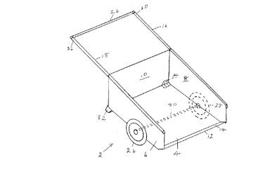
Referring to Figure 1 a wheelbarrow 2 is provided
with a bottom wall 4, two opposing side walls 6 and 8 and
a transverse rear wall 10 joining the side and bottom
walls. The bottom wall 4 is bevelled for a short distance
f rom its f ront edge 12 as shown at 14 whereby when a load
is dumped the apparatus r~sts on the edge rather than the
corners and is thus more durable. Two longitudinal handle
portions 16 and 18 e~tend rearwardly f rom each respective
side wall 6 or 8 and grip portions 20 and 22 are provided
at their free ends. For added strength, the handle
portion extend along the sides 6 and 8. A transverse
removable handle crosspiece 24 is shown e~tending between
the two handle portions 16 and 18. Grip portions 20 and
22 may extend beyond crosspieces 24.
A pair of wheels 26 and 28 are provided, one on
each side of the wheelbarl~ow or cart 2 and have a common
axle 30 which extends across the width of the wheelbarrow
on the underside of the bottom wall 4.
Feet 32 and 34 are provided and each e2tends
downwardly at a respective rear corner junction of the
bottom wall 4, rear wall 1~, and side wall 6 or 8.
In Figure 2 a third wheel 36 is provided of a
smaller diameter than wheels 26 and 28 and located
appro~imately centrally of the junction of the bottom wall
4 and the rear wall 10. This wheel may, of course, be a
detachable wheel and is sh~wn as a swivel wheel.
In Figure 3 the wheels 26 and 28 are each mounted
on a wheel hub, such as 38, attached to a mounting bracket
40 attached to the exterior of a respective side wall 6 or
8. This facilitates the adjustment of the wheel hub 38
between different vertical positions.
In Figure 4 a fork arrangement, such as 42, is
provided on each side of the wheelbarrow 2 for supporting
the wheels 26 and 28.
2181492
.
-- 3 --
In Figure 5 the f ront end o~ the wheelbarrow is
provided with a remova3~1e front wall 44 which i8 slidable
in groove members 46 and 418 attached to a respective side
wall 6 or 8.
It will be under.stood that the illustrated
wheelbarrow is easier to load since the front end sits
lower to the ground than previous wheelbarrows.
It will be readlly apparent to a person skilled in
the art that a number of ~rariations and modifications can
be made without departing from the true spirit of the
invention which will now 3~e pointed out in the appended
claims .