Language selection

Search

Patent 2186537 Summary

Third-party information liability

Some of the information on this Web page has been provided by external sources. The Government of Canada is not responsible for the accuracy, reliability or currency of the information supplied by external sources. Users wishing to rely upon this information should consult directly with the source of the information. Content provided by external sources is not subject to official languages, privacy and accessibility requirements.

Claims and Abstract availability

Any discrepancies in the text and image of the Claims and Abstract are due to differing posting times. Text of the Claims and Abstract are posted:

  • At the time the application is open to public inspection;
  • At the time of issue of the patent (grant).
(12) Patent: (11) CA 2186537
(54) English Title: TOOL HANDLE MOUNTING STRUCTURE FOR GARDEN TOOLS
(54) French Title: DISPOSITIF DE MONTAGE POUR ARTICLES DE JARDIN
Status: Deemed expired
Bibliographic Data
(51) International Patent Classification (IPC):
  • B25G 3/30 (2006.01)
  • A01B 1/22 (2006.01)
  • B25G 3/12 (2006.01)
  • B25G 3/18 (2006.01)
(72) Inventors :
  • HSU, CHUN-LI (Taiwan, Province of China)
(73) Owners :
  • HSU, CHUN-LI (Taiwan, Province of China)
(71) Applicants :
  • HSU, CHUN-LI (Taiwan, Province of China)
(74) Agent: KIRBY EADES GALE BAKER
(74) Associate agent:
(45) Issued: 1999-08-31
(22) Filed Date: 1996-09-26
(41) Open to Public Inspection: 1998-03-27
Examination requested: 1996-09-26
Availability of licence: N/A
(25) Language of filing: English

Patent Cooperation Treaty (PCT): No

(30) Application Priority Data: None

Abstracts

English Abstract


A tool handle mounting structure
including a tool head having a fixed coupling cap,
a handle having a tubular front end fastened to the
coupling cap by a screw joint, and a sleeve fixedly
mounted around the tubular front end to hold a
sliding lock, wherein when the sliding lock is
moved forwards after the handle is coupled to the
coupling cap of the tool head, the handle is
locked; when the sliding lock is moved backwards,
the handle is unlocked, and can be turned reversely
and disconnected from the coupling cap of the tool
head.


French Abstract

Cette invention concerne une monture de manche d'outil composée d'une tête d'outil à capuchon d'accouplement fixe, d'un manche à extrémité frontale tubulaire assujetti au capuchon de d'accouplement par vissage et d'un manchon fixe autour de ladite extrémité frontale tubulaire servant de support à un verrou coulissant. Ce verrou est poussé vers l'avant après vissage du manche dans le capuchon d'accouplement pour verrouiller le manche à la tête d'outil et ramené vers l'arrière pour déverrouiller le manche et permettre de la dévisser du capuchon d'accouplement.

Claims

Note: Claims are shown in the official language in which they were submitted.

-7-

I claim:
1. A tool handle mounting structure
comprising a tool head, a coupling cap having a
mounting section at one end fixed to said tool head
and a coupling section at an opposite end adapted
for coupling to a handle, said mounting section
having a steps raised from the periphery one above
another in direction toward said spirally grooved
coupling section, said coupling section having a
spiral groove around the periphery, and a handle
having a tubular front end adapted for coupling to
the coupling section of said coupling cap, wherein:
said handle has a plurality of threads
raised from its tubular front end on the inside and
adapted for threading onto the spiral groove of the
coupling section of said coupling cap;
said coupling cap has a longitudinal
locating groove at the highest step of said
mounting section;
a sleeve is fixedly mounted around the
tubular front end of said handle, having a
longitudinal track on the outside and a
longitudinal sliding slot in said longitudinal
track, said longitudinal sliding slot being
longitudinally aligned with the longitudinal


-8-

locating groove of said coupling cap when said
handle is coupled to said coupling cap;
a sliding lock is mounted in the
longitudinal sliding slot, and moved forwards and
backwards relative to the locating groove of said
coupling cap, said sliding lock being adapted for
moving forwards into the locating groove of said
coupling cap to prohibit rotary motion of said
sleeve and said handle relative to said coupling
cap and said tool head, or backwards from the
locating groove of said coupling cap to let said
sleeve and said handle to be turned relative to
said coupling cap and said tool head.


Description

Note: Descriptions are shown in the official language in which they were submitted.


21 86537

-
-1 -

TOOL HANDLE MOUNTING STRUCTURE FOR GARDEN TOOLS

BACKGROUND OF THE INVENTION
The present invention relates to
gardening tools, and relates more particularly to
the tool handle mounting structure of a gardening
tool which permits the handle to be quickly
fastened to the tool head, and releasably locked by
a sliding lock.

A variety of gardening tools including
spades, dibbles, rakes, mattocks, etc., are used in
nursery gardens for different purposes. Regular
gardening tools are commonly made in set. A
gardening tool set includes several gardening tools
of the same kind but respectively equipped with a
different length of handle for use in different
conditions. However, it is not economic to prepare
several gardening tools for the same purpose just
for use in different conditions. In order to
eliminate this problem, gardening tools with
replaceable handles are designed, and a screw joint
is commonly employed for the connection between the
handle and the tool head. Because the handle is
fastened to the tool head through a screw joint,
the handle tends to be turned relative to the tool

21 86537

--2--

head during operation, causing the tool head to
disconnect from the tool head.

SUNMARY OF THE INVENTION
The present invention has been
accomplished to provide a tool handle mounting
structure which eliminates the aforesaid problems.
It is the main object of the present invention to
provide a tool handle mounting structure which
permits the handle to be quickly coupled to the
tool head and, which locks the handle in position
when installed. According to the preferred
embodiment of the present invention, the toll
handle mounting structure is comprised of a tool
head having a fixed coupling cap, a handle having a
tubular front end fastened to the coupling cap by a
screw joint. The tubular front end of the handle is
mounted with a sleeve, which holds a sliding lock.
When the sliding lock is moved forwards into a
locating groove on the outside wall of the coupling
cap after the handle is coupled to the coupling cap
of the tool head, the handle is locked. On the
contrary, when the sliding lock is moved backwards,
the handle is unlocked, and can be turned reversely
and disconnected from the coupling cap of the tool

21 86537

--3--

head.

BRIEF DESCRIPTION OF THE DRAWINGS
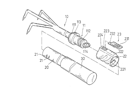
Fig. 1 is an exploded view of a toll
handle mounting structure according to one
embodiment of the present invention;
Fig. 2 is an assembly view of Figure 1,
Fig. 3A is a longitudinal view in
section of a part of Figure 2 in an enlarged scale,
showing the sliding lock locked, and,
Fig. 3B is similar to Figure 3A but
showing the sliding lock unlocked.
DETAILED DESCRIPTION OF THE PREFERRED EMBODIMENT
Referring to Figures 1 to 3, a tool
handle mounting structure in accordance with the
present invention is generally comprised of a tool
head 10, and a handle 20. The tool head 10 is
mounted with a coupling cap 11 adapted for coupling
to the handle 20. The coupling cap 11 is a
cylindrical cap having a mounting section 111 at
one end fixed to the tool head 10, and an
externally spirally grooved coupling section 112 at
an opposite end for coupling to the handle 20. The
outer diameter of the mounting section 111 has a
stepped profile raised in direction toward the

21 86537

-4-

coupling section 112. A longitudinal locating
groove 113 is formed at the biggest outer diameter
of the mounting section 111. A ring 114 is fixedly
connected to the free end of the coupling section
112 for hanging. The handle 20 has a hollow
cylindrical shape, a plurality of threads 21
radially raised from the inside wall near one end
~namely, the front end which is adapted for
coupling to coupling cap 11 at one end of the tool
head 10) and adapted for engaging the spirally
grooved outside wall of the coupling section 112 of
the coupling cap 11, and a grip 30 at an opposite
end (namely, the rear end remote from the too head
10). A sleeve 22 is mounted around the front end of
the handle 20. The sleeve 22 has a plurality of
radial oblong slots 221 axially spaced from one
another at one side, a longitudinal track 222
raised from the periphery at one side opposite to
the oblong slots 221, a longitudinal sliding slot
223 through the longitudinal track 222, a bridge
224 in front of the longitudinal sliding slot 223,
a sliding lock 23 mounted in the longitudinal
sliding slot 223. The radial oblong slots diminish
material consumption, reinforce the the structural
strength of the sleeve 22, and make the sleeve 22

21 86537
--5--

more attractive. The sliding lock 23 comprises a
push plate 231 moved along the longitudinal track
222 of the sleeve 22, and a locking tongue 232
extended forwards from the push plate 231 at a
different elevation and moved in the longitudinal
sliding slot 223 under the bridge 224.

Referring to Figures 3A and 3B, when the
front end of the handle 20 is fitted into the
sleeve 22, the front end of the handle 20 is
coupled to the coupling cap 11 by threading the
threads 21 onto the spirally grooved outside wall
of the coupling section 112 of the coupling cap 11.
When coupled, the push plate 231 of the sliding
lock 23 is pushed forwards to force the
longitudinal tongue 232 into the longitudinal
locating groove 113 to stop the sleeve 22 and the
handle 20 from rotary motion relative to coupling
cap 11, and therefore the handle 20 and the tool
head 10 are locked. When the push plate 231 is
pushed backwards to disengage the locking tongue
232 from the longitudinal locating groove 113, the
sleeve 22 and the handle 20 are unlocked and can be
turned relative to the coupling cap 11 in the
reversed direction, and therefore the handle 20 can

21 86537

-
-6-

be disconnected from the tool head 10.

While only one embodiment of the present
invention has been shown and described, it will be
understood that various modifications and changes
could be made thereunto without departing from the
spirit and scope of the invention disclosed.

Representative Drawing
A single figure which represents the drawing illustrating the invention.
Administrative Status

For a clearer understanding of the status of the application/patent presented on this page, the site Disclaimer , as well as the definitions for Patent , Administrative Status , Maintenance Fee  and Payment History  should be consulted.

Administrative Status

Title Date
Forecasted Issue Date 1999-08-31
(22) Filed 1996-09-26
Examination Requested 1996-09-26
(41) Open to Public Inspection 1998-03-27
(45) Issued 1999-08-31
Deemed Expired 2002-09-26

Abandonment History

There is no abandonment history.

Payment History

Fee Type Anniversary Year Due Date Amount Paid Paid Date
Application Fee $0.00 1996-09-26
Maintenance Fee - Application - New Act 2 1998-09-28 $50.00 1998-07-27
Final Fee $150.00 1999-05-27
Maintenance Fee - Application - New Act 3 1999-09-27 $50.00 1999-08-11
Maintenance Fee - Patent - New Act 4 2000-09-26 $50.00 2000-07-26
Owners on Record

Note: Records showing the ownership history in alphabetical order.

Current Owners on Record
HSU, CHUN-LI
Past Owners on Record
None
Past Owners that do not appear in the "Owners on Record" listing will appear in other documentation within the application.
Documents

To view selected files, please enter reCAPTCHA code :


To view images, click a link in the Document Description column. To download the documents, select one or more checkboxes in the first column and then click the "Download Selected in PDF format (Zip Archive)" or the "Download Selected as Single PDF" button.

List of published and non-published patent-specific documents on the CPD .

If you have any difficulty accessing content, you can call the Client Service Centre at 1-866-997-1936 or send them an e-mail at CIPO Client Service Centre.


Document
Description 
Date
(yyyy-mm-dd) 
Number of pages   Size of Image (KB) 
Representative Drawing 1999-08-23 1 13
Cover Page 1998-09-14 1 44
Cover Page 1997-01-23 1 13
Abstract 1997-01-23 1 16
Description 1997-01-23 6 169
Claims 1997-01-23 2 50
Drawings 1997-01-23 4 62
Cover Page 1999-08-23 1 46
Representative Drawing 1998-09-14 1 12
Correspondence 1999-05-27 1 38
Assignment 1996-09-26 3 156
Correspondence 1998-05-05 1 23
Prosecution-Amendment 1998-09-15 2 68