Language selection

Search

Patent 2187824 Summary

Third-party information liability

Some of the information on this Web page has been provided by external sources. The Government of Canada is not responsible for the accuracy, reliability or currency of the information supplied by external sources. Users wishing to rely upon this information should consult directly with the source of the information. Content provided by external sources is not subject to official languages, privacy and accessibility requirements.

Claims and Abstract availability

Any discrepancies in the text and image of the Claims and Abstract are due to differing posting times. Text of the Claims and Abstract are posted:

  • At the time the application is open to public inspection;
  • At the time of issue of the patent (grant).
(12) Patent Application: (11) CA 2187824
(54) English Title: DRAIN PAN FOR HOT WATER HEATERS AND WATER SOFTENERS
(54) French Title: COLLECTEUR POUR APPAREIL DE CHAUFFAGE A EAU CHAUDE OU ADOUCISSEUR D'EAU
Status: Dead
Bibliographic Data
Abstracts

English Abstract


A drain pan is used for collecting and draining off water leaking
from a water tank, for example a hot water tank or water softener that has
ruptured. The pan has a circular base panel and an annular skirt. A port in
the skirt connects directly to a hose that leads the leaking water to a floor
drain. To allow the pan to be installed under existing tank installations, it isdivided in two so that each half can be slid separately under the tank with
the tank tilted slightly to raise it from the floor. The two halves can then be
snapped together to form a complete water impervious pan.


French Abstract

Bac de récupération et de drainage d'eau fuyant d'un réservoir d'eau, par exemple un réservoir d'eau chaude ou un adoucisseur d'eau. Le bac est constitué d'un fond circulaire et d'une jupe circulaire. Une ouverture pratiquée dans la jupe permet un raccord direct à un boyau qui conduit l'eau jusqu'à un drain de plancher. Pour permettre d'installer le bac sous un réservoir déjà en place, le bac est divisé en deux parties afin que chacune d'elles puisse être glissée séparément sous le réservoir en le penchant légèrement de manière à le soulever du plancher. Les deux moitiés du bac sont encliquetables pour former un bac entièrement étanche à l'eau.

Claims

Note: Claims are shown in the official language in which they were submitted.


CLAIMS:
1. A drain pan for water tanks comprising a water
impervious base panel of corrosion resistant material, a water impervious
peripheral skirt of corrosion resistant material projecting upwardly from the
base panel and a drain port in the skirt, wherein the pan comprises two
components, each including respective portions of the base panel and the
skirt and coupling means for forming a water impervious coupling between
the two components.
2. A pan according to Claim 1 wherein the base pan is
substantially circular.
3. A pan according to Claim 2 wherein the skirt is
substantially cylindrical.
4. A drain pan according to Claim 3 wherein the
components are separated along a diameter of the base panel.
5. A drain pan according to Claim 4 wherein the coupling
means comprise a channel along an edge of one component and a mating
bead along an edge of the other component.
6. A drain pan according to Claim 5 including a gasket
seated in the channel.
7. A drain pan according to any one of Claims 1 through 6
wherein the drain pan comprises a plastics material.
8. A drain pan according to any one of Claims 1 through 6
wherein the drain port comprises a hose fitting for connection to a hose
end.
9. A method of installing a drain pan under a water tank,
said method comprising:
providing a drain pan with a base panel and a peripheral skirt
projecting upwardly from the base panel;


providing the drain pan in two components, each including
respective portions of the base panel and the skirt;
lifting one side of the tank;
sliding the base panel of one component under the one side of
the tank;
lifting an opposite side of the tank;
sliding the base panel part of the other component under said
opposite side of the tank;
bringing the two components together; and
sealing the two components together to form an impervious
drain pan.

Description

Note: Descriptions are shown in the official language in which they were submitted.


2 1 87824

DRAIN PAN FOR HOT WATER HEATERS AND WATER SO -lrN~S
The present invention relates to drain pans and more
particularly to drain pans for water tanks, for example, hot water tanks.
Water tanks, for example hot water tanks and water softener
tanks, are often located in finished areas of a building. In domestic uses,
5 these tanks are often located in finished basements. The tanks may corrode
over time and ultimately burst, discharging the enclosed water. This may
cause damage to carpets, finished walls and furnishings. To deal with this,
it has been known to place a sheet metal drain pan under a tank when it is
installed. The pan is drained by a hose to a floor drain. The value of these
10 metal pans is not particularly great since the metal pan may corrode and be
incapable of performing its intended function when needed.
This problem can be solved by using a plastic material for the
drain pan. Non-corroding plastic pans, like their metal predecessors, can
only be installed with new tanks, since the tank must physically be lifted
15 into the pan. This is prevented by both the weight of an in service water
tank and the plumbing connected to it.
The present invention is intended to ameliorate certain problems
with the prior art.
According to one aspect of the invention there is provided a
20 drain pan for water tanks comprising a water impervious base panel of
corrosion resistant material, a water impervious peripheral skirt of corrosion
resistant material projecting upwardly from the base panel and a drain port
in the skirt, wherein the pan comprises two components, each including
respective portions of the base panel and the skirt and coupling means for
25 forming a water impervious coupling between the two components.
By making the pan in two parts, it is possible to slip one part
under one or two feet of an installed tank by tipping the tank slightly, and
then to slip the other part under the tank in the same way. The two parts

2 1 87824


are then coupled to provide the complete, water impervious pan under the
tank. This installation is easily done, even as a retrofit to existing tanks.
The pan may be circular, with a cylindrical skirt. The two
components may then join along a diametrical seam. The coupling means
5 may be a channel on one component edge and a bead along the other.
Where desired, a gasket may be placed in the base of the channel to ensure
the water impervious nature of the pan.
In the accompanying drawings, which illustrate an exemplary
embodiment of the present invention:
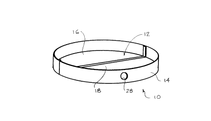
Figure 1 is an isometric view of a drain pan according to the
present invention.
Figure 2 is a cross section along the line 2-2 of Figure 1.
Figures 3A, 3B and 3C schematically illustrate the installation of
the drain pan under a water tank.
Referring to the accompanying drawings, there is illustrated a
drain pan 10 with a circular base panel 12 and an annular, cylindrical skirt
14 extending peripherally above the base panel. The base panel is divided
into two halves 16 and 18 along a diametrical seam. The seam is composed
of a channel 20 along the edge of pan half 16 and a mating bead 22 that
snaps into the re-entrant channel behind two lips 24 at the free edges of the
channel. The lips thus hold the bead firmly in place. A rod 26 of
compressible foam material is seated in the base of the channel as a gasket
to be engaged by the bead to ensure a water impervious seal between the
two components of the pan.
A threaded port 28 is formed in the skirt 14 and is sized for
coupling to a 3/4 inch (2 cm) hose.
The installation of the pan under a water tank is illustrated in
Figures 3A, 3B and 3C. The water tank 30 is tipped slightly to one side.

2 1 87824


Even with a plumbed in, full tank, this is usually possible to the extent that it
will lift a foot 32 of the tank off the floor on which it is resting sufficiently
that the base panel part of one component of the pan can be slid under the
foot to approximately the centre of the water tank. The tank can then be
5 tipped up to the other side to slide the other component of the pan under
the feet 32 of the tank. The two components of the pan are then snapped
together along the seam. A hose screwed into the port 28 leads to a floor
drain to drain off any liquid accumulating in the pan as the result of a
ruptured tank.
While one particular embodiment of the present invention has
been described in the foregoing, it is to be understood that other
embodiments are possible with the scope of the invention and are intended
to included herein. The invention is to be construed as limited solely by the
scope of the appended claims.
Representative Drawing
A single figure which represents the drawing illustrating the invention.
Administrative Status

For a clearer understanding of the status of the application/patent presented on this page, the site Disclaimer , as well as the definitions for Patent , Administrative Status , Maintenance Fee  and Payment History  should be consulted.

Administrative Status

Title Date
Forecasted Issue Date Unavailable
(22) Filed 1996-10-11
(41) Open to Public Inspection 1998-04-11
Dead Application 1999-10-12

Abandonment History

Abandonment Date Reason Reinstatement Date
1998-10-13 FAILURE TO PAY APPLICATION MAINTENANCE FEE

Payment History

Fee Type Anniversary Year Due Date Amount Paid Paid Date
Application Fee $0.00 1996-10-11
Owners on Record

Note: Records showing the ownership history in alphabetical order.

Current Owners on Record
CALL, GARTH J.
Past Owners on Record
None
Past Owners that do not appear in the "Owners on Record" listing will appear in other documentation within the application.
Documents

To view selected files, please enter reCAPTCHA code :


To view images, click a link in the Document Description column. To download the documents, select one or more checkboxes in the first column and then click the "Download Selected in PDF format (Zip Archive)" or the "Download Selected as Single PDF" button.

List of published and non-published patent-specific documents on the CPD .

If you have any difficulty accessing content, you can call the Client Service Centre at 1-866-997-1936 or send them an e-mail at CIPO Client Service Centre.


Document
Description 
Date
(yyyy-mm-dd) 
Number of pages   Size of Image (KB) 
Abstract 1997-03-06 1 14
Cover Page 1997-03-06 1 15
Description 1997-03-06 3 105
Drawings 1997-03-06 2 22
Claims 1997-03-06 2 44
Cover Page 1998-04-27 1 39
Cover Page 1999-09-30 1 39
Representative Drawing 1998-04-27 1 4
Prosecution Correspondence 1998-11-27 1 25
Office Letter 1996-11-14 1 30