Language selection

Search

Patent 2193188 Summary

Third-party information liability

Some of the information on this Web page has been provided by external sources. The Government of Canada is not responsible for the accuracy, reliability or currency of the information supplied by external sources. Users wishing to rely upon this information should consult directly with the source of the information. Content provided by external sources is not subject to official languages, privacy and accessibility requirements.

Claims and Abstract availability

Any discrepancies in the text and image of the Claims and Abstract are due to differing posting times. Text of the Claims and Abstract are posted:

  • At the time the application is open to public inspection;
  • At the time of issue of the patent (grant).
(12) Patent Application: (11) CA 2193188
(54) English Title: ADHESIVE TAPE DISPENSER
(54) French Title: DISTRIBUTEUR DE RUBAN ADHESIF
Status: Dead
Bibliographic Data
(51) International Patent Classification (IPC):
  • B65H 35/07 (2006.01)
  • B65H 35/00 (2006.01)
(72) Inventors :
  • HUANG, HARRSION (Taiwan, Province of China)
(73) Owners :
  • HUANG, HARRSION (Taiwan, Province of China)
(71) Applicants :
  • HUANG, HARRSION (Taiwan, Province of China)
(74) Agent: OSLER, HOSKIN & HARCOURT LLP
(74) Associate agent:
(45) Issued:
(22) Filed Date: 1996-12-17
(41) Open to Public Inspection: 1998-06-17
Availability of licence: N/A
(25) Language of filing: English

Patent Cooperation Treaty (PCT): No

(30) Application Priority Data: None

Abstracts

English Abstract


An adhesive tape dispenser comprises a main body, a shaft jacket and a
rotary wheel. The main body is composed of a handle, a cutter, and a
fixed shaft on which the shaft jacket is mounted for holding a small-size
adhesive tape roll. The rotary wheel is detachably mounted on the shaft
jacket for holding a large-size adhesive tape roll.


French Abstract

Cette invention concerne un distributeur de ruban adhésif composé d'un corps principal, d'une chemise et d'une roue libre. Le corps principal comprend une poignée, un coupe-ruban et un arbre fixe sur lequel est montée la chemise d'arbre destinée à recevoir un petit rouleau de ruban adhésif. La roue libre montée de façon amovible sur la chemise d'arbre sert à recevoir un rouleau de ruban adhésif de grand diamètre.

Claims

Note: Claims are shown in the official language in which they were submitted.


THE EMBODIMENTS OF THE INVENTION IN WHICH AN EXCLUSIVE
PROPERTY OR PRIVILEGE IS CLAIMED ARE DEFINED AS FOLLOWS:

1. An adhesive tape dispenser comprising:

a main body composed of a handle, a cutter, and a fixed shaft;
a shaft jacket of a tubular construction and provided in an outer
wall thereof with a plurality of parallel protruded rails extending in the
direction of a longitudinal axis of said shaft jacket, said shaft jacket
fitted pivotally over said fixed shaft of said main body for holding a
small-size adhesive tape roll; and

a rotary wheel having a center hole provided in an inner wall
thereof with a plurality of slide slots parallel to one another, said rotary
wheel being detachably mounted on said shaft jacket for holding a
large-size adhesive tape roll such that said shaft jacket is received in said
center hole of said rotary wheel, and that said slide slots of said rotary
wheel are engaged with said protruded rails of said shaft jacket.

2. The adhesive tape dispenser as defined in claim 1, wherein said
shaft jacket is provided at one end thereof with a cut; and wherein said
rotary wheel is provided in said center hole thereof with a suspended
elastic arm capable of deformation and having a retaining portion
engageable and disengageable with said cut of said shaft jacket.


Description

Note: Descriptions are shown in the official language in which they were submitted.


- 2 1 93 1 88


ADHESIVE TAPE DISPENSER


FIELD OF THE INVENTION

The present invention relates generally to an adhesive tape, and
more particularly to a device for dispensing the adhesive tape.


BACKGROUND OF THE INVENTION

The conventional adhesive tape dispenser is provided with a rotary
wheel, which is capable of accommodating only the adhesive tape roll of
a specific size. In other words, the conventional adhesive tape dispenser
does not fit the tape rolls of various sizes. This implies that a variety of
tape dispensers must be purchased for the adhesive tape rolls of various
sizes.


SUMMARY OF THE INVENTION

The primary objective of the present invention is therefore to


21 93~a

provide an adhesive tape dispenser with an adjustable means enabling
the adhesive tape dispenser to hold and dispense the adhesive tape rolls
of various sizes.

In keeping with the principle of the present invention, the
foregoing objective of the present invention is attained by an adhesive
tape dispenser, which comprises a main body, a shaft jacket, and a rotary
wheel. The main body has a handle, a cutter, and a fixed shaft. The shaft
jacket is fitted over the fixed shaft and is provided on the outer wall
thereof with a plurality of parallel rails to facilitate the mounting of the
tape rolls of smaller sizes. The rotary wheel is provided with an axial
hole having in the inner wall thereof a plurality of parallel sliding slots
engageable with the parallel rails of the shaft jacket.

The foregoing objective, features and advantages of the present
invention will be more readily understood upon a thoughtful deliberation
of the following detailed description of an embodiment of the present
invention in conjunction with the accompanying drawings.


BRIEF DESCRIPTION OF THE DRAWINGS

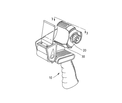
FIG. 1 shows a perspective view of the embodiment of the present
invention.

FIG. 2 shows an exploded view of the embodiment of the present
inventlon.

- ' 2193188
FIG. 3 shows a sectional view taken along the direction indicated
by a line 3-3 as shown in FIG. 1.

FIG. 4 shows a schematic view of the present invention at work.

FIG. 5 shows another schematic view of the present invention at
work.


DETATl,~l) DESCRIPTION OF THE INVENTION

The adhesive tape dispenser of the present invention comprises a
main body 10, a shaft jacket 20, and a rotary wheel 30, as shown in FIGS.
1 -3.

The main body 10 is composed o~ a handle 11, and a frame plate
12 which is provided with a cutter 13 and a fixed shaft 14 having a
threaded hole 141. The cutter 13 has a stopping piece 131, a cutting edge
132 and a roller 133.

The shaft jacket 20 is tubular in shape and is provided with an
axial hole 21 dimensioned to fit over the fixed shaft 14. The shaft jacket
20 is filrther provided with a receiving recess 22 in which a cushion ring
23, an inner press ring 24, a spring 25, and an outer press ring 26 are
located. The shaft jacket 20 is secured to the fixed shaft 14 by a
fastening bolt 27 engageable with the threaded hole 141 of the fixed
shaft 14. The shaft jacket 20 in motion is forced to bring about a
damping effect by the inner press ring 24 which is exerted on by a


2193188

rotational motion of the outer press ring 26. The shaft jacket 20 is
provided on the outer wall thereof with three protruded rails 28 parallel
to one another and extending along the direction of the longitudinal axis
of the shaft jacket 20. The rails 28 are intended for use in mounting the
adhesive tape rolls of small sizes. The shaft jacket 20 is further provided
with a plurality of cuts 29, which are located respectively at one end of
the shaft jacket 20 and between two rails 28.

The rotary wheel 30 has three projected portions 31 located in the
periphery thereof for accommodating the adhesive tape rolls of greater
sizes. The rotary wheel 30 is provided with a center hole 32 having in
the inner wall thereof three parallel slide slots 33 engageable with the
protruded rails 28 of the shaft jacket 20. The center hole 32 is
dimensioned to fit over the shaft jacket 20 such that the slide slots 33 are
engaged with the protruded rails 28. Located between two slide slots 33
is a suspended elastic arm 34 capable of deformation and having a
retaining portion 341 engageable with the cut 29 of the shaft jacket 20,
as illustrated in FIG. 3. The rotary wheel can be disengaged with the
shaft jacket 20 by forcing the ret~ining portion 341 of the deformable
elastic arm 34 to disengage the cut 29.

As shown in FIG. 4, the rotary wheel 30 of the present invention is
intended for use in mounting a large-size adhesive tape roll. On the other
hand, the shaft jacket 20 is intended for use in mounting a small-size
adhesive tape roll, as shown in FIG.5. The protruded rails 28 of the shaft
jacket 20 serve to locate the small-size adhesive tape roll which is
mounted on the shaft jacket 20.

The embodiment of the present invention described above is to be


- 21 931 88

regarded in all respects as being merely illustrative and not restrictive.
Accordingly, the present invention may be embodied in other specific
forms without deviating from the spirit thereof. The present invention is
therefore to be limited only by the scopes of the following appended
claims.
s
Representative Drawing
A single figure which represents the drawing illustrating the invention.
Administrative Status

For a clearer understanding of the status of the application/patent presented on this page, the site Disclaimer , as well as the definitions for Patent , Administrative Status , Maintenance Fee  and Payment History  should be consulted.

Administrative Status

Title Date
Forecasted Issue Date Unavailable
(22) Filed 1996-12-17
(41) Open to Public Inspection 1998-06-17
Dead Application 2001-12-17

Abandonment History

Abandonment Date Reason Reinstatement Date
2000-12-18 FAILURE TO PAY APPLICATION MAINTENANCE FEE

Payment History

Fee Type Anniversary Year Due Date Amount Paid Paid Date
Application Fee $0.00 1996-12-17
Maintenance Fee - Application - New Act 2 1998-12-17 $50.00 1998-12-14
Maintenance Fee - Application - New Act 3 1999-12-17 $50.00 1999-12-14
Owners on Record

Note: Records showing the ownership history in alphabetical order.

Current Owners on Record
HUANG, HARRSION
Past Owners on Record
None
Past Owners that do not appear in the "Owners on Record" listing will appear in other documentation within the application.
Documents

To view selected files, please enter reCAPTCHA code :


To view images, click a link in the Document Description column. To download the documents, select one or more checkboxes in the first column and then click the "Download Selected in PDF format (Zip Archive)" or the "Download Selected as Single PDF" button.

List of published and non-published patent-specific documents on the CPD .

If you have any difficulty accessing content, you can call the Client Service Centre at 1-866-997-1936 or send them an e-mail at CIPO Client Service Centre.


Document
Description 
Date
(yyyy-mm-dd) 
Number of pages   Size of Image (KB) 
Drawings 1997-04-22 3 67
Claims 1997-04-22 1 37
Representative Drawing 1998-06-17 1 9
Cover Page 1997-04-22 1 13
Abstract 1997-04-22 1 13
Description 1997-04-22 5 147
Cover Page 1998-06-17 1 34
Fees 1999-12-14 1 58
Fees 1998-12-14 1 62