Sélection de la langue

Search

Sommaire du brevet 2193188 

Énoncé de désistement de responsabilité concernant l'information provenant de tiers

Une partie des informations de ce site Web a été fournie par des sources externes. Le gouvernement du Canada n'assume aucune responsabilité concernant la précision, l'actualité ou la fiabilité des informations fournies par les sources externes. Les utilisateurs qui désirent employer cette information devraient consulter directement la source des informations. Le contenu fourni par les sources externes n'est pas assujetti aux exigences sur les langues officielles, la protection des renseignements personnels et l'accessibilité.

Disponibilité de l'Abrégé et des Revendications

L'apparition de différences dans le texte et l'image des Revendications et de l'Abrégé dépend du moment auquel le document est publié. Les textes des Revendications et de l'Abrégé sont affichés :

  • lorsque la demande peut être examinée par le public;
  • lorsque le brevet est émis (délivrance).
(12) Demande de brevet: (11) CA 2193188
(54) Titre français: DISTRIBUTEUR DE RUBAN ADHESIF
(54) Titre anglais: ADHESIVE TAPE DISPENSER
Statut: Morte
Données bibliographiques
(51) Classification internationale des brevets (CIB):
  • B65H 35/07 (2006.01)
  • B65H 35/00 (2006.01)
(72) Inventeurs :
  • HUANG, HARRSION (Taïwan, Province de Chine)
(73) Titulaires :
  • HUANG, HARRSION (Taïwan, Province de Chine)
(71) Demandeurs :
  • HUANG, HARRSION (Taïwan, Province de Chine)
(74) Agent: OSLER, HOSKIN & HARCOURT LLP
(74) Co-agent:
(45) Délivré:
(22) Date de dépôt: 1996-12-17
(41) Mise à la disponibilité du public: 1998-06-17
Licence disponible: S.O.
(25) Langue des documents déposés: Anglais

Traité de coopération en matière de brevets (PCT): Non

(30) Données de priorité de la demande: S.O.

Abrégés

Abrégé français

Cette invention concerne un distributeur de ruban adhésif composé d'un corps principal, d'une chemise et d'une roue libre. Le corps principal comprend une poignée, un coupe-ruban et un arbre fixe sur lequel est montée la chemise d'arbre destinée à recevoir un petit rouleau de ruban adhésif. La roue libre montée de façon amovible sur la chemise d'arbre sert à recevoir un rouleau de ruban adhésif de grand diamètre.


Abrégé anglais


An adhesive tape dispenser comprises a main body, a shaft jacket and a
rotary wheel. The main body is composed of a handle, a cutter, and a
fixed shaft on which the shaft jacket is mounted for holding a small-size
adhesive tape roll. The rotary wheel is detachably mounted on the shaft
jacket for holding a large-size adhesive tape roll.

Revendications

Note : Les revendications sont présentées dans la langue officielle dans laquelle elles ont été soumises.


THE EMBODIMENTS OF THE INVENTION IN WHICH AN EXCLUSIVE
PROPERTY OR PRIVILEGE IS CLAIMED ARE DEFINED AS FOLLOWS:

1. An adhesive tape dispenser comprising:

a main body composed of a handle, a cutter, and a fixed shaft;
a shaft jacket of a tubular construction and provided in an outer
wall thereof with a plurality of parallel protruded rails extending in the
direction of a longitudinal axis of said shaft jacket, said shaft jacket
fitted pivotally over said fixed shaft of said main body for holding a
small-size adhesive tape roll; and

a rotary wheel having a center hole provided in an inner wall
thereof with a plurality of slide slots parallel to one another, said rotary
wheel being detachably mounted on said shaft jacket for holding a
large-size adhesive tape roll such that said shaft jacket is received in said
center hole of said rotary wheel, and that said slide slots of said rotary
wheel are engaged with said protruded rails of said shaft jacket.

2. The adhesive tape dispenser as defined in claim 1, wherein said
shaft jacket is provided at one end thereof with a cut; and wherein said
rotary wheel is provided in said center hole thereof with a suspended
elastic arm capable of deformation and having a retaining portion
engageable and disengageable with said cut of said shaft jacket.


Description

Note : Les descriptions sont présentées dans la langue officielle dans laquelle elles ont été soumises.


- 2 1 93 1 88


ADHESIVE TAPE DISPENSER


FIELD OF THE INVENTION

The present invention relates generally to an adhesive tape, and
more particularly to a device for dispensing the adhesive tape.


BACKGROUND OF THE INVENTION

The conventional adhesive tape dispenser is provided with a rotary
wheel, which is capable of accommodating only the adhesive tape roll of
a specific size. In other words, the conventional adhesive tape dispenser
does not fit the tape rolls of various sizes. This implies that a variety of
tape dispensers must be purchased for the adhesive tape rolls of various
sizes.


SUMMARY OF THE INVENTION

The primary objective of the present invention is therefore to


21 93~a

provide an adhesive tape dispenser with an adjustable means enabling
the adhesive tape dispenser to hold and dispense the adhesive tape rolls
of various sizes.

In keeping with the principle of the present invention, the
foregoing objective of the present invention is attained by an adhesive
tape dispenser, which comprises a main body, a shaft jacket, and a rotary
wheel. The main body has a handle, a cutter, and a fixed shaft. The shaft
jacket is fitted over the fixed shaft and is provided on the outer wall
thereof with a plurality of parallel rails to facilitate the mounting of the
tape rolls of smaller sizes. The rotary wheel is provided with an axial
hole having in the inner wall thereof a plurality of parallel sliding slots
engageable with the parallel rails of the shaft jacket.

The foregoing objective, features and advantages of the present
invention will be more readily understood upon a thoughtful deliberation
of the following detailed description of an embodiment of the present
invention in conjunction with the accompanying drawings.


BRIEF DESCRIPTION OF THE DRAWINGS

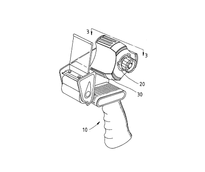
FIG. 1 shows a perspective view of the embodiment of the present
invention.

FIG. 2 shows an exploded view of the embodiment of the present
inventlon.

- ' 2193188
FIG. 3 shows a sectional view taken along the direction indicated
by a line 3-3 as shown in FIG. 1.

FIG. 4 shows a schematic view of the present invention at work.

FIG. 5 shows another schematic view of the present invention at
work.


DETATl,~l) DESCRIPTION OF THE INVENTION

The adhesive tape dispenser of the present invention comprises a
main body 10, a shaft jacket 20, and a rotary wheel 30, as shown in FIGS.
1 -3.

The main body 10 is composed o~ a handle 11, and a frame plate
12 which is provided with a cutter 13 and a fixed shaft 14 having a
threaded hole 141. The cutter 13 has a stopping piece 131, a cutting edge
132 and a roller 133.

The shaft jacket 20 is tubular in shape and is provided with an
axial hole 21 dimensioned to fit over the fixed shaft 14. The shaft jacket
20 is filrther provided with a receiving recess 22 in which a cushion ring
23, an inner press ring 24, a spring 25, and an outer press ring 26 are
located. The shaft jacket 20 is secured to the fixed shaft 14 by a
fastening bolt 27 engageable with the threaded hole 141 of the fixed
shaft 14. The shaft jacket 20 in motion is forced to bring about a
damping effect by the inner press ring 24 which is exerted on by a


2193188

rotational motion of the outer press ring 26. The shaft jacket 20 is
provided on the outer wall thereof with three protruded rails 28 parallel
to one another and extending along the direction of the longitudinal axis
of the shaft jacket 20. The rails 28 are intended for use in mounting the
adhesive tape rolls of small sizes. The shaft jacket 20 is further provided
with a plurality of cuts 29, which are located respectively at one end of
the shaft jacket 20 and between two rails 28.

The rotary wheel 30 has three projected portions 31 located in the
periphery thereof for accommodating the adhesive tape rolls of greater
sizes. The rotary wheel 30 is provided with a center hole 32 having in
the inner wall thereof three parallel slide slots 33 engageable with the
protruded rails 28 of the shaft jacket 20. The center hole 32 is
dimensioned to fit over the shaft jacket 20 such that the slide slots 33 are
engaged with the protruded rails 28. Located between two slide slots 33
is a suspended elastic arm 34 capable of deformation and having a
retaining portion 341 engageable with the cut 29 of the shaft jacket 20,
as illustrated in FIG. 3. The rotary wheel can be disengaged with the
shaft jacket 20 by forcing the ret~ining portion 341 of the deformable
elastic arm 34 to disengage the cut 29.

As shown in FIG. 4, the rotary wheel 30 of the present invention is
intended for use in mounting a large-size adhesive tape roll. On the other
hand, the shaft jacket 20 is intended for use in mounting a small-size
adhesive tape roll, as shown in FIG.5. The protruded rails 28 of the shaft
jacket 20 serve to locate the small-size adhesive tape roll which is
mounted on the shaft jacket 20.

The embodiment of the present invention described above is to be


- 21 931 88

regarded in all respects as being merely illustrative and not restrictive.
Accordingly, the present invention may be embodied in other specific
forms without deviating from the spirit thereof. The present invention is
therefore to be limited only by the scopes of the following appended
claims.
s
Dessin représentatif
Une figure unique qui représente un dessin illustrant l'invention.
États administratifs

Pour une meilleure compréhension de l'état de la demande ou brevet qui figure sur cette page, la rubrique Mise en garde , et les descriptions de Brevet , États administratifs , Taxes périodiques et Historique des paiements devraient être consultées.

États administratifs

Titre Date
Date de délivrance prévu Non disponible
(22) Dépôt 1996-12-17
(41) Mise à la disponibilité du public 1998-06-17
Demande morte 2001-12-17

Historique d'abandonnement

Date d'abandonnement Raison Reinstatement Date
2000-12-18 Taxe périodique sur la demande impayée

Historique des paiements

Type de taxes Anniversaire Échéance Montant payé Date payée
Le dépôt d'une demande de brevet 0,00 $ 1996-12-17
Taxe de maintien en état - Demande - nouvelle loi 2 1998-12-17 50,00 $ 1998-12-14
Taxe de maintien en état - Demande - nouvelle loi 3 1999-12-17 50,00 $ 1999-12-14
Titulaires au dossier

Les titulaires actuels et antérieures au dossier sont affichés en ordre alphabétique.

Titulaires actuels au dossier
HUANG, HARRSION
Titulaires antérieures au dossier
S.O.
Les propriétaires antérieurs qui ne figurent pas dans la liste des « Propriétaires au dossier » apparaîtront dans d'autres documents au dossier.
Documents

Pour visionner les fichiers sélectionnés, entrer le code reCAPTCHA :


Pour visualiser une image, cliquer sur un lien dans la colonne description du document. Pour télécharger l'image (les images), cliquer l'une ou plusieurs cases à cocher dans la première colonne et ensuite cliquer sur le bouton "Télécharger sélection en format PDF (archive Zip)" ou le bouton "Télécharger sélection (en un fichier PDF fusionné)".

Liste des documents de brevet publiés et non publiés sur la BDBC .

Si vous avez des difficultés à accéder au contenu, veuillez communiquer avec le Centre de services à la clientèle au 1-866-997-1936, ou envoyer un courriel au Centre de service à la clientèle de l'OPIC.


Description du
Document 
Date
(yyyy-mm-dd) 
Nombre de pages   Taille de l'image (Ko) 
Dessins 1997-04-22 3 67
Revendications 1997-04-22 1 37
Dessins représentatifs 1998-06-17 1 9
Page couverture 1997-04-22 1 13
Abrégé 1997-04-22 1 13
Description 1997-04-22 5 147
Page couverture 1998-06-17 1 34
Taxes 1999-12-14 1 58
Taxes 1998-12-14 1 62