Language selection

Search

Patent 2194703 Summary

Third-party information liability

Some of the information on this Web page has been provided by external sources. The Government of Canada is not responsible for the accuracy, reliability or currency of the information supplied by external sources. Users wishing to rely upon this information should consult directly with the source of the information. Content provided by external sources is not subject to official languages, privacy and accessibility requirements.

Claims and Abstract availability

Any discrepancies in the text and image of the Claims and Abstract are due to differing posting times. Text of the Claims and Abstract are posted:

  • At the time the application is open to public inspection;
  • At the time of issue of the patent (grant).
(12) Patent: (11) CA 2194703
(54) English Title: VENTILATION SYSTEM
(54) French Title: SYSTEME DE VENTILATION
Status: Deemed expired
Bibliographic Data
Abstracts

English Abstract


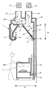
A ventilation system having a hood located above cooking equipment which generates
heat and fumes due to cooking. The hood has an inclined air filter at the back of the hood which
rests on a flange extending along the length of the hood at the top thereof and the bottom of the
inclined air filter rests on a grease collector extending along the length of the hood. The grease
collector is located at a given distance downwardly from the top of the hood. The back of the
inclined air filter defines an exhaust area, and the hood also includes an exhaust duct being in
direct communication with the exhaust area and a fan for drawing the contaminated air out of the
exhaust area. The hood also has a fresh air output that is connected to a fresh air duct including
a fan and located along the length of the hood at the front thereof, this fresh air output being
designed to inject fresh air into the hood. The invention is characterized in that the fresh air
output of the hood is positioned to direct fresh air towards the inclined air filter at an upwards
angle with respect to horizontal. The system further has a fresh air diffuser located behind the
cooking equipment and near the floor, connected to the fresh air duct and being devised to diffuse
air upwardly and downwardly. In use, the fresh air output forces the contaminated air to exit
through the filter as it directs a steady stream of fresh air towards the filter. The fresh air diffuser
feeds fresh air downwardly, which increases the burner efficiency of the cooking equipment and
upwardly at the back of the cooking equipment, which creates air movement towards the hood
reducing the amount of stale air that is present near the floor and behind the cooking equipment.


French Abstract

Système de ventilation comprenant une hotte disposée au-dessus de l'équipement de cuisson qui dégage de la chaleur et des émanations en raison de la cuisson. La hotte comprend un filtre à air incliné posé à l'arrière et qui prend appui sur un rebord s'étendant sur la longueur de la hotte, dans sa partie supérieure; la partie inférieure du filtre à air incliné repose sur un collecteur de graisse qui s'avance sur toute la longueur de la hotte. Le collecteur de graisse est placé à une distance donnée sous la partie supérieure de la hotte. L'arrière du filtre à air incliné définit une section d'évacuation et la hotte comprend également un conduit d'évacuation en communication directe avec la section d'évacuation et un ventilateur pour aspirer l'air contaminé hors de la section d'évacuation. La hotte comprend également un point de sortie d'air frais raccordé à un conduit d'air frais comprenant un ventilateur et passant le long de la hotte, à l'avant de celle-ci; ce point de sortie d'air frais est conçu pour permettre l'injection d'air dans la hotte. L'invention se distingue par le fait que le point de sortie d'air frais de la hotte est placé de façon à diriger le jet d'air frais vers le filtre incliné à un angle ascendant par rapport à un plan horizontal. De plus, le système comprend un diffuseur d'air frais placé derrière l'équipement de cuisson, près du plancher, raccordé au conduit d'air frais et divisé de façon à diffuser l'air vers le haut et vers le bas. Lorsqu'il est en service, le point de sortie d'air frais oblige l'air contaminé à sortir en passant par le filtre puisqu'il dirige un jet constant d'air frais vers le filtre. Le diffuseur d'air frais pousse de l'air frais vers le bas ce qui améliore l'efficacité du brûleur de l'équipement de cuisson et il pousse également de l'air vers le haut, à l'arrière de l'équipement de cuisson, ce qui crée un mouvement de l air vers la hotte, réduisant ainsi le volume d'air vicié présent près du plancher et derrière l'équipement de cuisson.

Claims

Note: Claims are shown in the official language in which they were submitted.


WHAT IS CLAIMED IS:

1. ~A ventilation system for use with cooking equipment
resting on a floor, said system comprising:
- a hood located above said cooking equipment, said hood
having a front, a back and a length and including an
inclined air filter at said back, said inclined air filter
having a front, a back, a top and a bottom, where said top
of said inclined air filter rests on a flange extending
along said length of said hood at the top thereof and said
bottom of said inclined air filter rests on a grease
collector extending along said length of said hood, said
grease collector being located at a given distance
downwardly from said top of said hood, the back of said
inclined air filter defining an exhaust area, said hood
also including an exhaust duct that is in direct
communication with said exhaust area and includes exhaust
means, said hood further having a fresh air output
operatively connected to a fresh air duct including fan
means, said fresh air output being located along said
length of said hood at the front thereof and being designed
to inject fresh air into the hood, said fresh air output of
said hood being positioned to direct fresh air towards said
inclined air filter at an upwards angle with respect to
horizontal, characterized in that:
- said system further comprises at least one adjustable
fresh air diffuser, said at least one adjustable fresh air
diffuser being located behind said cooking equipment and
generally adjacent said floor, said at least one fresh air
diffuser being operatively connected to said fresh air duct


7


and being devised to diffuse air upwardly and downwardly in
predetermined proportions.

2. A system according to claim 1, wherein said fresh air
output has a longitudinal opening having a width
substantially equal to one inch, said opening extending
along said length of said hood.

3. A system according to claim 2, wherein said upwards
angle is equal to about 45°.

4. A system according to claim 1, wherein said grease
collector has two opposite ends and a cross-sectional shape
in the form of a generally rounded gutter, and wherein said
grease collector is provided with a plug adjacent one of
said opposite ends, said one opposite end being located at
a height lower than the other one of said opposite ends.

5. A system according to claim 2, wherein said grease
collector has two opposite ends and a cross-sectional shape
in the form of a generally rounded gutter, and wherein said
grease collector is provided with a plug adjacent one of
said opposite ends, said one opposite end being located at
a height lower than the other one of said opposite ends.

6. A system according to claim 3, wherein said grease
collector has two opposite ends and a cross-sectional shape
in the form of a generally rounded gutter, and wherein said
grease collector is provided with a plug adjacent one of
said opposite ends, said one opposite end being located at
a height lower than the other one of said opposite ends.


8


7. A ventilation system for use with cooking equipment
resting on a floor, said system comprising:

- a hood located above said cooking equipment, said hood
having a front, a back and a length and including an
inclined air filter at said back, said inclined air filter
having a front, a back, a top and a bottom, where said top
of said inclined air filter rests on a flange extending
along said length of said hood at the top thereof and said
bottom of said inclined air filter rests on a grease
collector extending along said length of said hood, said
grease collector being located at a given distance
downwardly from said top of said hood, the back of said
inclined air filter defining an exhaust area, said hood
also including an exhaust duct that is in direct
communication with said exhaust area and includes exhaust
means, said hood further having a fresh air output
operatively connected to a fresh air duct including fan
means, said fresh air output being located along said
length of said hood at the front thereof and being designed
to inject fresh air into the hood, said fresh air output of
said hood being positioned to direct fresh air towards said
inclined air filter at an upwards angle with respect to
horizontal, characterized in that:

- said system further comprises at least one fresh air
diffuser, said at least one fresh air diffuser being
located behind said cooking equipment and generally
adjacent said floor, said at least one fresh air diffuser
being operatively connected to said fresh air duct and
being devised to diffuse air upwardly and downwardly in
predetermined proportions.


9

Description

Note: Descriptions are shown in the official language in which they were submitted.


CA 02194703 1998-04-30


VENTILATION SYSTEM

FIELD OF THE INVENTION

The present invention relates to a ventilation system, and more particularly to a ventilation
system for use in a cooking area.

DESCRIPTION OF THE PRIOR ART

It is well known in the art to use hoods to ventilate cooking areas. Most of these hoods
include an intake funnel, a fan connected to the intake funnel and an exhaust pipe. They also
include a filter which must be changed or cleaned periodically. The hoods are usually located
above the cooking areas in order to properly ventilate the same.
However, when such hoods are used in commercial cooking areas such as restaurants,
some problems are associated with them. First of all, the heat generated by commercial cooking
areas is much greater than by domestic areas. Therefore, the volume of air that must be evacuated
is thus increased. Furthermore, since the fumes are sucked out of the area, there exists the
possibility of stale air ~ g at the bottom of the cooking equipment, which can create health
problems and reduce the efficiency of the cooking equipment.
Such hoods also have a tendency to evacuate the commercial cooking area's ambient air,
i.e. air conditioned air in the summertime and heated air in the wintertime, which results in uneven
heat distribution on the floor or high heating bills, and which may even affect the heat distribution
in the dining area.
In some cases, particularly commercial cooking areas, hoods are further provided with
means to force fresh air towards the filter and thus increase the air flow, hereinafter referred to
as the fresh air technique. This is done to help overcome the above-noted problem. The most
common method of introducing fresh air is to either blow the air horizontally towards the filter
or vertically downwardly.
A major problem associated with the horizontal forced fresh air technique is that unless
it is properly balanced, it may create air inversion, which instead of evac~l~ting the fumes and
smoke, actually traps them inside the cooking area, particularly in the wintertime. Users have

CA 02194703 1998-04-30

_
attempted to overcome this problem by altogether blocking the fresh air in the wintertime, which
returns the user to the original problem of having ambient air evacuated.
If the air is blown vertically, it may create discomfort for the cooks using the cooking
equipment.
There thus exists a need for a ventilation system which obviates the above-noted problems
in the prior art.

SUMMARY OF THE INVENTION

It is thus an object of the invention to provide a ventilation system for use with cooking
equipment located on a floor which increases the air flow, is more efficient, may reduce the
amount of stale air located at the bottom of the cooking equipment, is easier to clean and
minimi7es the amount of ambient air that is evacll~ted
In accordance with the invention, this object is achieved with a ventilation system
15 comprising a hood located above the cooking equipment. The hood has a front, a back and a
length and includes an inclined air filter at the back of the hood. The inclined air filter has a front,
a back, a top and a bottom, where the top of the inclined air filter rests on a flange extending
along the length of the hood at the top thereof and the bottom of the inclined air filter rests on a
grease collector .o.xtçn~1ing along the length ofthe hood. The grease collector is located at a given
20 distance downwardly from the top of the hood. The back of the inclined air filter defines an
exhaust area, and the hood also includes an exhaust duct being in direct communication with the
exhaust area. The hood also includes exhaust means for drawing the cont~min~ted air out of the
exhaust area. The hood is further provided with a fresh air output that is operatively connected
to a fresh air duct including fan means and located along the length of the hood at the front
25 thereof, this fresh air output being designed to inject fresh air into the hood.
The invention is characterized in that the fresh air output of the hood is positioned to
direct fresh air towards the inclined air filter at an upwards angle with respect to horizontal.
Preferably, the system further comprises at least one fresh air diffuser located behind the
cooking equipment and generally adjacent the floor, the at least one fresh air diffuser being
30 operatively connected to the fresh air duct and being designed to diffuse air upwardly and
downwardly in predetermined proportions.

CA 02194703 1998-04-30
-


In use, the cooking appal~lus will generate heat and fumes due to cooking, hereinafter
referred to as cont~tnin~ted air. These rise naturally towards the hood. The fresh air output
further forces the co~ ted air to exit through the filter as it directs a steady stream of fresh
air towards the filter. Furthermore, the fresh air diffuser feeds fresh air downwardly, which
5 increases the burner efficiency of the cooking equipment. The fresh air diffuser further feeds fresh
air towards the hood at the back of the cooking equipment, which creates air movement towards
the hood, thereby reducing the amount of stale air that may be present near the floor and behind
the cooking equipment and increases the air flow towards the filter and out of the establishment.
One ofthe important advantages of the invention is that the fresh air that is inputted into
10 the hood and at the bottom of the cooking equipment does not need to be heated or cooled.
Furthermore, the fresh air is delivered in such a way that the burners of the cooking equipment
burn more cleanly and efficiently.

BRIEF DESCRIPTION OF THE DRAWINGS
The present invention and its advantages will be more easily understood after reading the
following non-restrictive description of prer~led embodiments thereof, made with reference to
the following drawings in which:
Figure 1 is a cross-sectional side elevational view of a ventilation system according to a
20 plt;relled embodiment ofthe invention;
Figure 2 is a detailed cross-sectional side view of the fresh air diffuser; and
Figure 3 is front schematic representation of the hood of Fig. 1.

DESCRIPTION OF A PREFERRED EMBODIMENT OF THE INVENTION
The ventilation system according to the pl erel I ed embodiment of the invention shown in
the accompanying drawings includes as its main component a hood 1. Figure 1 shows is a cross-
sectional side view of the hood 1 according to the invention. As seen in Fig. 1, the hood is
located above cooking equipment 2 which rests on a floor. The cooking equipment 2 can be a
30 grill, a fryer, an oven, etc. When the cooking equipment 2 is in use, it produces a mixture of heat,
grease and fumes, referred to as cont~rnin~ted air 4.


.~ .

CA 02194703 1998-04-30
.

The hood 1 has a top 5, a bottom 7, a front 9, a back 11, two opposite sides 13, a length
15, a width 17, a height 19, a fresh air intake duct 23 and an exhaust duct 25, both located at the
top 5 of the hood 1. The height 19 is preferably a minimllm of 30 inches.
The hood 1 has a fresh air output 33, along its length at the front 9 thereof and an inclined
5 filter 35 at the back thereof 11. The inclined filter 35 has a front 37, a back 39, a top 41 and a
bottom 43. The top 41 ofthe inclined filter 35 rests on a flange 45, extending along the length
15 of the hood 1, the flange 45 being located at the top 5 of the hood 1 approximately halfway
- between the front 9 and the back 11. The bottom 43 of the inclined filter 35 rests on a grease
collector 47, also extending along the length 15 of the hood 1, the grease collector 47 being
10 located at a given distance downwardly from the top 5 of the hood 1. Preferably, as can be seen
on Figure 1, the grease collector 47 has the cross-sectional shape of a generally rounded gutter
so as to better collect the grease dripping from the filter 35 and to make it easier to clean.
Preferably, the grease collector 47 is inclined with respect to the horizontal so as to channel the
grease towards a proper collector 48, or stopper, at one or the other side of the hood 1. Thus,
15 the grease collector has two opposite ends, one of which is provided with a collector or stopper,
and which is also lower than the other opposite end (see Fig. 3, in dotted lines).
The back 39 of the filter 35 defines an exhaust area 49 which is in direct communication
with the exhaust duct 25.
The fresh air output 33 is in direct communication with the fresh air intake duct 23 and
20 directs fresh air 34 towards the filter 35. Preferably, the fresh air output 33 is angled upwardly
in order to not create an air inversion, which would trap the cont~min~ted air over the cooking
apparatus 2. It has been found that the most efficient angle is 45~. Also preferably, the fresh air
output 33 is provided with a longitudinal opening of approximately one inch.
As better shown on Figure 2, at least one fresh air diffuser 31, is located near the floor.
25 The fresh air diffuser 31 is in direct communication with the fresh air intake duct 23 and includes
adiffuser 101 forrliffi1singfreshair34verticallytowardsthetop 5 ofthehood 1 andvertically
downwardly in predetermined proportions. The diffuser includes an air splitter 103 which splits
air between the two vertical directions. The diffuser 101 has an input 105 connected to the fresh
air duct 23 and two outputs 107, 109. The diffuser and the air splitter are preferably made of
30 al..mini~-m The diffuser 101 is fastened to the wall. The proportion of air that is directed in each
vertical direction can be adjusted by adjusting the vertical location of the air splitter 103.


" ' r ~

CA 02194703 1998-04-30
-


The fresh air intake duct 23 includes a ventilator 111 for injecting fresh air 34 into the
system and feeding it to the fresh air output 33 and to the fresh air diffuser 31. As better shown
on Figure 3, the fresh air intake duct 23 (in dotted lines) feeds fresh air 34 into the fresh air
output 33 through three secondary ducts 24 which can be appropriately placed according to the
S user's needs. It should be noted that the number of secondary ducts 24 are a function of the
length of the hood 15 and are adequately placed in order to provide optimal air flow.
The fresh air intake duct 23 also feeds fresh air 34 through at least one other secondary
duct 26 to the fresh air diffuser 31. The secondary ducts 24, 26 are properly in~ul~ted so as to
permit the gradual heating of the fresh air 34 during the winter in order to avoid condensation and
10 to prevent inconvenience to the users. It should be noted that, depending on the length of the
hood 1, the ventilation system may include more than one fresh air diffuser 31, which are
appropriately placed in order to provide optimal burn for the cooking equipment.The exhaust duct 25 includes a ventilator 113 for forcing co~ 1 ed air out of the hood
1 and to the outside ofthe cooking area. The exhaust duct includes a domed exit 36 located in
15 the middle of the hood 1 as better shown on Figure 3. The dimensions of the domed exit 36 are
calculated according to standard air volume displacement requirements. The domed exit 36 has
a shape which lessens the strain on the ventilator as it naturally pulls the cont~min~ted air 4
upwardly towards the ventilator.
In use, when a user 200 uses the cooking apparatus 2, cont~min~ted air 4 is produced
20 which must be evacll~ted The cont~min~ted air 4 rises naturally towards the top of the hood 1
and towards the filter 35. The fresh air output 33 further forces the cont~min~ted air 4 to exit
through the filter 35 as it directs a steady stream of fresh air 34 towards the filter 35
Furthermore, the fresh air diffuser 31 feeds fresh air vertically through the output 109, which
increases the burner efficiency ofthe cooking apparatus 2. The fresh air diffuser 31 further feeds
25 fresh air 34 vertically through output 107, which creates air movement towards the top S of the
hood 1, thereby reducing the amount of stale air that may be present near the floor and increasing
the air flow towards the filter and out of the establishment. The ventilation system as described
has the additional advantage of drawing minim~l air from the rest of the establishment, as it pulls
sufficient air fed from the fresh air output 33 and the fresh air diffuser 31.
The ventilation system as described above is efficient, worker friendly, environmentally
friendly and inexpensive to install and operate.


~ 1
,, .

CA 02194703 1998-04-30


One of the important aspects of the invention is that the fresh air that is inputted into the
hood and at the bottom of the cooking equipment does not need to be heated or cooled and is
delivered in such a way to the burners of the cooking equipment that the burners burn more
cleanly and efficiently.
It should be noted that the sizes of ductwork and openings of entry or exit of required air
volumes are readily calculable for an expert in the field, and thus no detail is provided herein.
AISo7 in order to meet standard requirements for safety, the secondary ducts 24 may be provided
with fire dampers 201.
Although the present invention has been explained hereinabove by way of a preferred
embodiment thereof, it should be pointed out that any modifications to this preferred embodiment
is not deemed to alter or change the nature and scope of the present invention, as defined in the
appended claims.


.~

Representative Drawing
A single figure which represents the drawing illustrating the invention.
Administrative Status

For a clearer understanding of the status of the application/patent presented on this page, the site Disclaimer , as well as the definitions for Patent , Administrative Status , Maintenance Fee  and Payment History  should be consulted.

Administrative Status

Title Date
Forecasted Issue Date 2003-06-10
(22) Filed 1997-01-08
Examination Requested 1998-01-08
(41) Open to Public Inspection 1998-07-08
(45) Issued 2003-06-10
Deemed Expired 2016-01-08

Abandonment History

There is no abandonment history.

Payment History

Fee Type Anniversary Year Due Date Amount Paid Paid Date
Application Fee $0.00 1997-01-08
Request for Examination $200.00 1998-01-08
Registration of a document - section 124 $100.00 1998-01-08
Maintenance Fee - Application - New Act 2 1999-01-08 $50.00 1999-01-07
Maintenance Fee - Application - New Act 3 2000-01-10 $50.00 2000-01-07
Maintenance Fee - Application - New Act 4 2001-01-08 $50.00 2001-01-04
Maintenance Fee - Application - New Act 5 2002-01-08 $75.00 2002-01-04
Maintenance Fee - Application - New Act 6 2003-01-08 $75.00 2003-01-08
Final Fee $150.00 2003-03-25
Maintenance Fee - Patent - New Act 7 2004-01-08 $100.00 2004-01-08
Maintenance Fee - Patent - New Act 8 2005-01-10 $100.00 2005-01-10
Maintenance Fee - Patent - New Act 9 2006-01-09 $100.00 2006-01-06
Maintenance Fee - Patent - New Act 10 2007-01-08 $125.00 2007-01-08
Maintenance Fee - Patent - New Act 11 2008-01-08 $125.00 2007-12-07
Maintenance Fee - Patent - New Act 12 2009-01-08 $125.00 2009-01-08
Maintenance Fee - Patent - New Act 13 2010-01-08 $125.00 2010-01-07
Maintenance Fee - Patent - New Act 14 2011-01-10 $125.00 2011-01-07
Maintenance Fee - Patent - New Act 15 2012-01-09 $225.00 2012-01-09
Maintenance Fee - Patent - New Act 16 2013-01-08 $225.00 2013-01-08
Maintenance Fee - Patent - New Act 17 2014-01-08 $225.00 2014-01-08
Owners on Record

Note: Records showing the ownership history in alphabetical order.

Current Owners on Record
KO-NIK EQUIPMENT INC.
Past Owners on Record
GEORGARAS, STAVROS
Past Owners that do not appear in the "Owners on Record" listing will appear in other documentation within the application.
Documents

To view selected files, please enter reCAPTCHA code :


To view images, click a link in the Document Description column. To download the documents, select one or more checkboxes in the first column and then click the "Download Selected in PDF format (Zip Archive)" or the "Download Selected as Single PDF" button.

List of published and non-published patent-specific documents on the CPD .

If you have any difficulty accessing content, you can call the Client Service Centre at 1-866-997-1936 or send them an e-mail at CIPO Client Service Centre.


Document
Description 
Date
(yyyy-mm-dd) 
Number of pages   Size of Image (KB) 
Cover Page 2003-05-07 2 55
Claims 2002-05-28 3 123
Claims 1997-04-29 1 8
Drawings 1997-04-29 2 34
Cover Page 1998-07-09 2 92
Cover Page 1997-04-29 1 13
Abstract 1997-04-29 1 13
Description 1997-04-29 5 252
Abstract 1998-04-30 1 40
Description 1998-04-30 6 293
Claims 1998-04-30 2 67
Drawings 1998-04-30 2 33
Representative Drawing 1998-07-09 1 8
Representative Drawing 2001-11-21 1 9
Fees 2004-01-08 1 29
Fees 2000-01-07 1 32
Fees 2009-01-08 1 41
Fees 2001-01-04 1 27
Fees 2003-01-08 1 29
Correspondence 2003-03-25 1 30
Correspondence 2007-01-09 2 74
Prosecution-Amendment 2002-05-28 6 200
Fees 2002-01-04 1 34
Fees 1999-01-07 1 34
Correspondence 1998-01-08 3 108
Assignment 1997-01-08 8 236
Prosecution-Amendment 1998-01-08 11 380
Correspondence 1997-02-19 1 25
Prosecution-Amendment 2001-11-28 2 36
Fees 2005-01-10 1 27
Fees 2006-01-06 1 29
Fees 2007-01-08 1 42
Fees 2007-12-07 1 45
Fees 2010-01-07 1 35
Correspondence 2010-08-10 1 45
Fees 2011-01-07 1 36
Fees 2012-01-09 1 38
Fees 2013-01-08 1 41
Fees 2014-01-08 1 39