Note : Les descriptions sont présentées dans la langue officielle dans laquelle elles ont été soumises.
CA 02194703 1998-04-30
VENTILATION SYSTEM
FIELD OF THE INVENTION
The present invention relates to a ventilation system, and more particularly to a ventilation
system for use in a cooking area.
DESCRIPTION OF THE PRIOR ART
It is well known in the art to use hoods to ventilate cooking areas. Most of these hoods
include an intake funnel, a fan connected to the intake funnel and an exhaust pipe. They also
include a filter which must be changed or cleaned periodically. The hoods are usually located
above the cooking areas in order to properly ventilate the same.
However, when such hoods are used in commercial cooking areas such as restaurants,
some problems are associated with them. First of all, the heat generated by commercial cooking
areas is much greater than by domestic areas. Therefore, the volume of air that must be evacuated
is thus increased. Furthermore, since the fumes are sucked out of the area, there exists the
possibility of stale air ~ g at the bottom of the cooking equipment, which can create health
problems and reduce the efficiency of the cooking equipment.
Such hoods also have a tendency to evacuate the commercial cooking area's ambient air,
i.e. air conditioned air in the summertime and heated air in the wintertime, which results in uneven
heat distribution on the floor or high heating bills, and which may even affect the heat distribution
in the dining area.
In some cases, particularly commercial cooking areas, hoods are further provided with
means to force fresh air towards the filter and thus increase the air flow, hereinafter referred to
as the fresh air technique. This is done to help overcome the above-noted problem. The most
common method of introducing fresh air is to either blow the air horizontally towards the filter
or vertically downwardly.
A major problem associated with the horizontal forced fresh air technique is that unless
it is properly balanced, it may create air inversion, which instead of evac~l~ting the fumes and
smoke, actually traps them inside the cooking area, particularly in the wintertime. Users have
CA 02194703 1998-04-30
_
attempted to overcome this problem by altogether blocking the fresh air in the wintertime, which
returns the user to the original problem of having ambient air evacuated.
If the air is blown vertically, it may create discomfort for the cooks using the cooking
equipment.
There thus exists a need for a ventilation system which obviates the above-noted problems
in the prior art.
SUMMARY OF THE INVENTION
It is thus an object of the invention to provide a ventilation system for use with cooking
equipment located on a floor which increases the air flow, is more efficient, may reduce the
amount of stale air located at the bottom of the cooking equipment, is easier to clean and
minimi7es the amount of ambient air that is evacll~ted
In accordance with the invention, this object is achieved with a ventilation system
15 comprising a hood located above the cooking equipment. The hood has a front, a back and a
length and includes an inclined air filter at the back of the hood. The inclined air filter has a front,
a back, a top and a bottom, where the top of the inclined air filter rests on a flange extending
along the length of the hood at the top thereof and the bottom of the inclined air filter rests on a
grease collector .o.xtçn~1ing along the length ofthe hood. The grease collector is located at a given
20 distance downwardly from the top of the hood. The back of the inclined air filter defines an
exhaust area, and the hood also includes an exhaust duct being in direct communication with the
exhaust area. The hood also includes exhaust means for drawing the cont~min~ted air out of the
exhaust area. The hood is further provided with a fresh air output that is operatively connected
to a fresh air duct including fan means and located along the length of the hood at the front
25 thereof, this fresh air output being designed to inject fresh air into the hood.
The invention is characterized in that the fresh air output of the hood is positioned to
direct fresh air towards the inclined air filter at an upwards angle with respect to horizontal.
Preferably, the system further comprises at least one fresh air diffuser located behind the
cooking equipment and generally adjacent the floor, the at least one fresh air diffuser being
30 operatively connected to the fresh air duct and being designed to diffuse air upwardly and
downwardly in predetermined proportions.
CA 02194703 1998-04-30
-
In use, the cooking appal~lus will generate heat and fumes due to cooking, hereinafter
referred to as cont~tnin~ted air. These rise naturally towards the hood. The fresh air output
further forces the co~ ted air to exit through the filter as it directs a steady stream of fresh
air towards the filter. Furthermore, the fresh air diffuser feeds fresh air downwardly, which
5 increases the burner efficiency of the cooking equipment. The fresh air diffuser further feeds fresh
air towards the hood at the back of the cooking equipment, which creates air movement towards
the hood, thereby reducing the amount of stale air that may be present near the floor and behind
the cooking equipment and increases the air flow towards the filter and out of the establishment.
One ofthe important advantages of the invention is that the fresh air that is inputted into
10 the hood and at the bottom of the cooking equipment does not need to be heated or cooled.
Furthermore, the fresh air is delivered in such a way that the burners of the cooking equipment
burn more cleanly and efficiently.
BRIEF DESCRIPTION OF THE DRAWINGS
The present invention and its advantages will be more easily understood after reading the
following non-restrictive description of prer~led embodiments thereof, made with reference to
the following drawings in which:
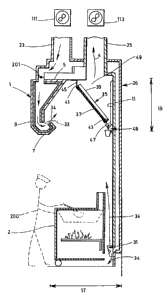
Figure 1 is a cross-sectional side elevational view of a ventilation system according to a
20 plt;relled embodiment ofthe invention;
Figure 2 is a detailed cross-sectional side view of the fresh air diffuser; and
Figure 3 is front schematic representation of the hood of Fig. 1.
DESCRIPTION OF A PREFERRED EMBODIMENT OF THE INVENTION
The ventilation system according to the pl erel I ed embodiment of the invention shown in
the accompanying drawings includes as its main component a hood 1. Figure 1 shows is a cross-
sectional side view of the hood 1 according to the invention. As seen in Fig. 1, the hood is
located above cooking equipment 2 which rests on a floor. The cooking equipment 2 can be a
30 grill, a fryer, an oven, etc. When the cooking equipment 2 is in use, it produces a mixture of heat,
grease and fumes, referred to as cont~rnin~ted air 4.
.~ .
CA 02194703 1998-04-30
.
The hood 1 has a top 5, a bottom 7, a front 9, a back 11, two opposite sides 13, a length
15, a width 17, a height 19, a fresh air intake duct 23 and an exhaust duct 25, both located at the
top 5 of the hood 1. The height 19 is preferably a minimllm of 30 inches.
The hood 1 has a fresh air output 33, along its length at the front 9 thereof and an inclined
5 filter 35 at the back thereof 11. The inclined filter 35 has a front 37, a back 39, a top 41 and a
bottom 43. The top 41 ofthe inclined filter 35 rests on a flange 45, extending along the length
15 of the hood 1, the flange 45 being located at the top 5 of the hood 1 approximately halfway
- between the front 9 and the back 11. The bottom 43 of the inclined filter 35 rests on a grease
collector 47, also extending along the length 15 of the hood 1, the grease collector 47 being
10 located at a given distance downwardly from the top 5 of the hood 1. Preferably, as can be seen
on Figure 1, the grease collector 47 has the cross-sectional shape of a generally rounded gutter
so as to better collect the grease dripping from the filter 35 and to make it easier to clean.
Preferably, the grease collector 47 is inclined with respect to the horizontal so as to channel the
grease towards a proper collector 48, or stopper, at one or the other side of the hood 1. Thus,
15 the grease collector has two opposite ends, one of which is provided with a collector or stopper,
and which is also lower than the other opposite end (see Fig. 3, in dotted lines).
The back 39 of the filter 35 defines an exhaust area 49 which is in direct communication
with the exhaust duct 25.
The fresh air output 33 is in direct communication with the fresh air intake duct 23 and
20 directs fresh air 34 towards the filter 35. Preferably, the fresh air output 33 is angled upwardly
in order to not create an air inversion, which would trap the cont~min~ted air over the cooking
apparatus 2. It has been found that the most efficient angle is 45~. Also preferably, the fresh air
output 33 is provided with a longitudinal opening of approximately one inch.
As better shown on Figure 2, at least one fresh air diffuser 31, is located near the floor.
25 The fresh air diffuser 31 is in direct communication with the fresh air intake duct 23 and includes
adiffuser 101 forrliffi1singfreshair34verticallytowardsthetop 5 ofthehood 1 andvertically
downwardly in predetermined proportions. The diffuser includes an air splitter 103 which splits
air between the two vertical directions. The diffuser 101 has an input 105 connected to the fresh
air duct 23 and two outputs 107, 109. The diffuser and the air splitter are preferably made of
30 al..mini~-m The diffuser 101 is fastened to the wall. The proportion of air that is directed in each
vertical direction can be adjusted by adjusting the vertical location of the air splitter 103.
" ' r ~
CA 02194703 1998-04-30
-
The fresh air intake duct 23 includes a ventilator 111 for injecting fresh air 34 into the
system and feeding it to the fresh air output 33 and to the fresh air diffuser 31. As better shown
on Figure 3, the fresh air intake duct 23 (in dotted lines) feeds fresh air 34 into the fresh air
output 33 through three secondary ducts 24 which can be appropriately placed according to the
S user's needs. It should be noted that the number of secondary ducts 24 are a function of the
length of the hood 15 and are adequately placed in order to provide optimal air flow.
The fresh air intake duct 23 also feeds fresh air 34 through at least one other secondary
duct 26 to the fresh air diffuser 31. The secondary ducts 24, 26 are properly in~ul~ted so as to
permit the gradual heating of the fresh air 34 during the winter in order to avoid condensation and
10 to prevent inconvenience to the users. It should be noted that, depending on the length of the
hood 1, the ventilation system may include more than one fresh air diffuser 31, which are
appropriately placed in order to provide optimal burn for the cooking equipment.The exhaust duct 25 includes a ventilator 113 for forcing co~ 1 ed air out of the hood
1 and to the outside ofthe cooking area. The exhaust duct includes a domed exit 36 located in
15 the middle of the hood 1 as better shown on Figure 3. The dimensions of the domed exit 36 are
calculated according to standard air volume displacement requirements. The domed exit 36 has
a shape which lessens the strain on the ventilator as it naturally pulls the cont~min~ted air 4
upwardly towards the ventilator.
In use, when a user 200 uses the cooking apparatus 2, cont~min~ted air 4 is produced
20 which must be evacll~ted The cont~min~ted air 4 rises naturally towards the top of the hood 1
and towards the filter 35. The fresh air output 33 further forces the cont~min~ted air 4 to exit
through the filter 35 as it directs a steady stream of fresh air 34 towards the filter 35
Furthermore, the fresh air diffuser 31 feeds fresh air vertically through the output 109, which
increases the burner efficiency ofthe cooking apparatus 2. The fresh air diffuser 31 further feeds
25 fresh air 34 vertically through output 107, which creates air movement towards the top S of the
hood 1, thereby reducing the amount of stale air that may be present near the floor and increasing
the air flow towards the filter and out of the establishment. The ventilation system as described
has the additional advantage of drawing minim~l air from the rest of the establishment, as it pulls
sufficient air fed from the fresh air output 33 and the fresh air diffuser 31.
The ventilation system as described above is efficient, worker friendly, environmentally
friendly and inexpensive to install and operate.
~ 1
,, .
CA 02194703 1998-04-30
One of the important aspects of the invention is that the fresh air that is inputted into the
hood and at the bottom of the cooking equipment does not need to be heated or cooled and is
delivered in such a way to the burners of the cooking equipment that the burners burn more
cleanly and efficiently.
It should be noted that the sizes of ductwork and openings of entry or exit of required air
volumes are readily calculable for an expert in the field, and thus no detail is provided herein.
AISo7 in order to meet standard requirements for safety, the secondary ducts 24 may be provided
with fire dampers 201.
Although the present invention has been explained hereinabove by way of a preferred
embodiment thereof, it should be pointed out that any modifications to this preferred embodiment
is not deemed to alter or change the nature and scope of the present invention, as defined in the
appended claims.
.~