Language selection

Search

Patent 2201513 Summary

Third-party information liability

Some of the information on this Web page has been provided by external sources. The Government of Canada is not responsible for the accuracy, reliability or currency of the information supplied by external sources. Users wishing to rely upon this information should consult directly with the source of the information. Content provided by external sources is not subject to official languages, privacy and accessibility requirements.

Claims and Abstract availability

Any discrepancies in the text and image of the Claims and Abstract are due to differing posting times. Text of the Claims and Abstract are posted:

  • At the time the application is open to public inspection;
  • At the time of issue of the patent (grant).
(12) Patent: (11) CA 2201513
(54) English Title: PROCEDURE AND APPARATUS FOR THE DRAINAGE OF THE WIRE AND/OR PRESS SECTION OF A PAPER MACHINE OR EQUIVALENT
(54) French Title: PROCEDE ET APPAREIL D'EVACUATION DE L'EAU DE LA SECTION TOILE ET/OU PRESSE D'UNE MACHINE A PAPIER OU ANALOGUE
Status: Expired
Bibliographic Data
(51) International Patent Classification (IPC):
  • D21F 1/48 (2006.01)
(72) Inventors :
  • KARVINEN, JUHA (Finland)
(73) Owners :
  • ECOPUMP OY (Finland)
(71) Applicants :
  • ECOPUMP OY (Finland)
(74) Agent: GOWLING LAFLEUR HENDERSON LLP
(74) Associate agent:
(45) Issued: 2007-01-30
(86) PCT Filing Date: 1995-09-22
(87) Open to Public Inspection: 1996-04-25
Examination requested: 2001-12-14
Availability of licence: N/A
(25) Language of filing: English

Patent Cooperation Treaty (PCT): Yes
(86) PCT Filing Number: PCT/FI1995/000521
(87) International Publication Number: WO1996/012064
(85) National Entry: 1997-04-01

(30) Application Priority Data:
Application No. Country/Territory Date
944796 Finland 1994-10-12

Abstracts

English Abstract


Paper drainage and drying is required in modern high
speed paper machines where the number of suction boxes is
limited. The present method provides a procedure for the
drainage of the wire and/or press section of a paper
machine, in which procedure at least one gap and the
suction pipe is connected to a vacuum device to develop a
vacuum at least in this vacuum pipe, and in which
procedure a felt, wire or equivalent is moved over the
gap of the suction pipe, water being thus drained from
the felt, wire or equivalent. In the procedure, the
vacuum capacity is adjusted by measuring and/or adjusting
at least the amount of water drained from the suction
pipe and, on the basis of the measured data, adjusting
the vacuum capacity by means of regulating devices. The
invention also relates to an apparatus for adjusting the
vacuum capacity.


French Abstract

Procédé d'évacuation de l'eau de la section toile et/ou presse d'une machine à papier, selon lequel au moins un tuyau d'aspiration (1) est pourvu d'au moins un orifice (2), et raccordé à un dispositif à vide (4) servant à faire le vide au moins dans ce tuyau d'aspiration. En outre, selon le procédé, on fait passer sur l'orifice du tuyau d'aspiration un feutre, une toile ou analogue, l'eau étant de ce fait évacuée du feutre, de la toile ou analogue. Selon ledit procédé, on règle le degré de dépression en mesurant et/ou en réglant au moins la quantité d'eau évacuée par le tuyau d'aspiration (1) et, en fonction des données mesurées, on règle le degré de dépression à l'aide de dispositifs de régulation (11, 12). On a également prévu un appareil de réglage du degré de dépression.

Claims

Note: Claims are shown in the official language in which they were submitted.


5


CLAIMS

1. A method for draining an amount of water from the
wire and/or press section of a paper machine including a
carrier for a wet web of paper, at least one roller over
which the carrier passes, at least one suction pipe
having at least one inlet adjacent the carrier, and a
vacuum device, having a vacuum capacity, connected to the
suction pipe for developing a vacuum in the suction pipe,
the method comprising the steps of:
draining a first amount of water from the web
carrier through the suction pipe;
determining first data representative of the first
amount of water drained;
draining by centrifugal force a second amount of
water from said roller into a collecting element;
determining second data representative of the second
amount of water drained; and
adjusting the vacuum capacity based on the first and
second data so as to control overall drainage from the
machine.
2. The method of claim T wherein the adjusting step
comprises, at least in part, adjusting the vacuum
capacity in the suction pipe by adjusting at least one
valve element disposed between the suction pipe and the
vacuum device of the paper machine.
3. The method of claim 1 wherein the adjusting step
comprises periodically operating the vacuum device.


6


4. The method of claim 1 wherein the adjusting step
comprises adjusting the rotational speed of the vacuum
device.
5. The method of claim 1 wherein the adjusting step
comprises varying the rotational speed of a centrifugal
fan disposed below the suction pipe.
5. The method of claim 1 wherein the adjusting step
comprises adjusting the vacuum capacity according to
preprogrammed data.
7. The method of claim 6 wherein said preprogrammed
data is based on a drainage ratio between water drained
through the suction pipe and water drained into the
collecting element, the ratio being adjustable by manual
or automatic means.
8. The method of claim 1 wherein the adjusting step
comprises adjusting the vacuum capacity by use of a
control unit.
9. The method of claim 1 wherein the adjusting step
comprises varying the position of the static vanes of a
centrifugal fan on the suction and pressure sides of said
fan.
10. An apparatus for draining the wire and/or press
section of a paper machine, comprising:
a wet paper web carrier;
at least one roller over which the carrier passes;
at least one suction pipe having at least one inlet
over which the carrier passes;


7


a water collecting element disposed below the
roller;
at least one vacuum device, having a vacuum
capacity, connected to the suction pipe by one or more
pipe elements;
means for moving the web carrier over the inlet of
the suction pipe for drying a paper web carried by the
carrier;
means connected to said pipe elements for
determining first data representative of an amount of
water drained from the suction pipe;
means connected to said collecting element for
determining second data representative of an amount of
water flowing from the collector element; and
means connected to said vacuum-device for adjusting
the vacuum capacity of the vacuum device, based on the
first and second data.
11. The apparatus of claim 10 wherein the adjusting
means comprises regulating devices.
12. The apparatus of claim 11 wherein the regulating
devices comprise a control unit and at least one valve
element.
13. The apparatus of claim 12 wherein the valve element
comprises at least one throttle valve and/or a
replacement air valve.

Description

Note: Descriptions are shown in the official language in which they were submitted.


CA 02201513 2005-06-03
1
PROCEDURE AND APPARATUS FOR THE DRAINAGE OF THE WIRE AND/OR
PRESS SECTION OF A PAPER MACHINE OR EQUIVALENT
The present invention relates to a procedure and to an
apparatus for the drainage of the wire and/or press section
of a paper machine.
In the paper industry, drainage is implemented using suction
pipes, suction boxes, suction rollers or equivalent provided
with longitudinal gaps or holes against a wire screen, felt
or equivalent. Each suction pipe i~~ so placed that the
wire, felt or equivalent passes over the gap or holes and
drying is effected as the water is hurled by a centrifugal
force into the roller trough. The water is gathered in the
suction pipe and passed to a suitable collecting place. An
apparatus of this type is presented in. US Patent 4,329,201.
In current systems, the vacuum is adjusted on the basis of
pressure, by using various valve elements or by varying the
rotational speed of a pump unit to maintain a desired
pressure. Of the processes in a paper machine, the vacuum
system is responsible for the highest power consumption. It
also has an effect on the driving output and steam
consumption of the press and wire section. In the solutions
currently used, the adjustment of the vacuum capacity
affects the negative pressure, but it has not been possible
to reliably determine the effect of t:he adjustment on the
drainage of the paper machine. An excessively high vacuum
level is not beneficial to drainage. Instead, it increases
the pumping costs and the costs resull~ing from the wear of
fabrics and consumption of energy caused by increased
friction.
The object of the present invention is to achieve a
completely new solution that allows the: drawbacks of known


WO 96/12064 PCTIFI95/00521
2
technology to be avoided.
The invention is based on an idea according to which the
vacuum capacity is adjusted on the basis of water volume
measurements with the aid of preprogrammed data. More
particularly, the invention is characterized by what is
presented in the claims.
The solution of- the invention has numerous significant
advantages. It makes it possible to control the drainage of
a paper machine so that an optimal drainage situation is
reached, with the result that the solids content e.g. after
the press section is maximized. Therefore, maximal drainage
for the wire and felt type in use is achieved. The
runnability of the paper machine is improved. An adjustable
vacuum system allows considerable savings to be made in
energy consumption and has advantageous effects on paper
quality.
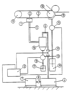
In the following, the invention is described by referring
to the attached drawing, which is a diagrammatic
representation of an apparatus as provided by the
invention.
The figure shows a simplified form of an apparatus for the
drainage of the wire and/or press section of a paper
machine. The apparatus comprises at least one suction pipe
1 having at least one gap 2 over which the felt, wire or
equivalent 3 passes, vacuum elements 4, piping elements 5,
6 connecting the suction pipe 1 to the vacuum elements 4,
drive elements 7, 8 for operating the vacuum devices 4 and
creating a vacuum in the suction pipe, and elements 9, 10
for moving the felt, wire or equivalent over the suction
pipe, thereby developing a vacuum for the drying of the
felt, wire or equivalent. The apparatus is provided with


WO 96/12064 ~ ~ ~ '~ 5 '~ PCT/FI95/00521
3
regulating elements 11, 12 for the adjustment of the vacuum
capacity and elements 13 at least in the suction~pipe for
the measurement and/or adjustment of the amount of water
drained, on the basis of which the vacuum capacity is
adjusted by means of the regulating elements.
'Vacuum capacity' refers to a value which equals negative
pressure (p) * pump yield value (Q).
The suction pipe 1 is placed in the apparatus in a manner
known in itself and it has a gap 2 that opens towards the
felt, wire or equivalent 3 passing over it. Connected to
the suction pipe 1 is a pipe 5 whose one end communicates
with the hollow space of a separator 16. From the lower end
IS of the separator, a pipe 18 extends downwards to a
container 17. The water flows in the pipe 18 under the
influence of gravity. Alternatively, a centrifugal pump
(not shown) can be mounted in conjunction with the pipe 18,
constituting a so-called extraction pump system. A pipe 6
starting from the upper end of the separator is connected
at its other end to the vacuum element 4, preferably a
vacuum pump. The pump 4 is operated by means of the drive
elements 7, 8.
The regulating elements consist of a control unit 12 and at
least one valve element 11. The control unit 12 is
preferably a process computer or equivalent. The valve
element 11 preferably consists of at least one throttle
valve and/or a replacement air valve. The valve element 11
is placed in the piping between the suction pipe 1 and the
" vacuum device 4 preferably near the suction pipe, most
preferably in the pipe 6 between the pump 4 and the
separator 16.
The apparatus comprises a collecting element 15, preferably


WU 96112064 PCT/FI95I00521
4
a so-called nip water trough, into which the water is
hurled by a centrifugal force.
The apparatus is provided with measuring devices 13 for the
measurement of the amount of water drained. The measuring
element that measures the amount of water drained from the
suction pipe 1 is preferably placed in pipe 18 between the
collecting element 15 and the container 19 or the like.
The control unit 12 may consist e.g. of a process computer
connected to receive the data supplied by the water meters
13, 14 and to adjust the vacuum capacity on the basis of
these data. The adjustment of the vacuum capacity is
controlled on the basis of information adjusted according
to the water measurements or on the basis of preprogrammed
information. The control unit preferably regulates the
valve element 11 and/or the drive 7 of the pump 4. The
vacuum capacity is adjusted in the suction piping by means
of .the valve element 11 and/or periodic operation of the
pump 4 and/or by adjusting the speed of rotation of the
vacuum pump 4 and/or by varying the rotational speed of the
centrifugal fan or the position of the static vanes on its
suction and pressure sides. With the solution of the
invention, the ratio of the amounts of water drained from
the suction pipe 1 and the collecting element 15 can be
adjusted or programmed.
It is obvious to the person skilled in the art that the
invention is not restricted to the application example
described above, but that it may instead be varied within
the scope of the following claims.

Representative Drawing
A single figure which represents the drawing illustrating the invention.
Administrative Status

For a clearer understanding of the status of the application/patent presented on this page, the site Disclaimer , as well as the definitions for Patent , Administrative Status , Maintenance Fee  and Payment History  should be consulted.

Administrative Status

Title Date
Forecasted Issue Date 2007-01-30
(86) PCT Filing Date 1995-09-22
(87) PCT Publication Date 1996-04-25
(85) National Entry 1997-04-01
Examination Requested 2001-12-14
(45) Issued 2007-01-30
Expired 2015-09-22

Abandonment History

There is no abandonment history.

Payment History

Fee Type Anniversary Year Due Date Amount Paid Paid Date
Registration of a document - section 124 $100.00 1997-04-01
Application Fee $150.00 1997-04-01
Maintenance Fee - Application - New Act 2 1997-09-22 $50.00 1997-07-21
Maintenance Fee - Application - New Act 3 1998-09-22 $50.00 1998-08-14
Maintenance Fee - Application - New Act 4 1999-09-22 $50.00 1999-08-12
Maintenance Fee - Application - New Act 5 2000-09-22 $75.00 2000-07-24
Maintenance Fee - Application - New Act 6 2001-09-24 $75.00 2001-08-02
Request for Examination $200.00 2001-12-14
Maintenance Fee - Application - New Act 7 2002-09-23 $75.00 2002-07-22
Maintenance Fee - Application - New Act 8 2003-09-22 $150.00 2003-09-08
Maintenance Fee - Application - New Act 9 2004-09-22 $200.00 2004-08-27
Maintenance Fee - Application - New Act 10 2005-09-22 $250.00 2005-08-26
Maintenance Fee - Application - New Act 11 2006-09-22 $250.00 2006-08-23
Final Fee $300.00 2006-11-14
Expired 2019 - Corrective payment/Section 78.6 $725.00 2006-12-19
Maintenance Fee - Patent - New Act 12 2007-09-24 $250.00 2007-08-23
Maintenance Fee - Patent - New Act 13 2008-09-22 $250.00 2008-08-25
Maintenance Fee - Patent - New Act 14 2009-09-22 $250.00 2009-09-10
Maintenance Fee - Patent - New Act 15 2010-09-22 $450.00 2010-09-09
Maintenance Fee - Patent - New Act 16 2011-09-22 $450.00 2011-09-08
Maintenance Fee - Patent - New Act 17 2012-09-24 $450.00 2012-09-07
Maintenance Fee - Patent - New Act 18 2013-09-23 $450.00 2013-09-09
Maintenance Fee - Patent - New Act 19 2014-09-22 $450.00 2014-09-05
Owners on Record

Note: Records showing the ownership history in alphabetical order.

Current Owners on Record
ECOPUMP OY
Past Owners on Record
KARVINEN, JUHA
Past Owners that do not appear in the "Owners on Record" listing will appear in other documentation within the application.
Documents

To view selected files, please enter reCAPTCHA code :


To view images, click a link in the Document Description column. To download the documents, select one or more checkboxes in the first column and then click the "Download Selected in PDF format (Zip Archive)" or the "Download Selected as Single PDF" button.

List of published and non-published patent-specific documents on the CPD .

If you have any difficulty accessing content, you can call the Client Service Centre at 1-866-997-1936 or send them an e-mail at CIPO Client Service Centre.


Document
Description 
Date
(yyyy-mm-dd) 
Number of pages   Size of Image (KB) 
Representative Drawing 2006-05-11 1 7
Abstract 1997-04-01 1 53
Representative Drawing 1997-07-02 1 3
Description 1997-04-01 4 176
Claims 1997-04-01 2 83
Drawings 1997-04-01 1 13
Cover Page 1997-07-02 1 47
Abstract 2005-06-03 1 33
Description 2005-06-03 4 184
Claims 2005-06-03 3 112
Cover Page 2007-01-04 2 46
Assignment 1997-04-01 3 118
PCT 1997-04-01 7 265
Correspondence 1997-04-29 1 39
Assignment 1997-04-14 2 46
Assignment 1997-06-05 1 20
Prosecution-Amendment 2001-12-14 1 27
Prosecution-Amendment 2002-02-14 1 32
Fees 2003-09-08 1 35
Fees 1999-08-12 1 28
Fees 1997-07-21 1 34
Fees 1998-08-14 1 34
Fees 2001-08-02 1 24
Fees 2002-07-22 1 44
Fees 2000-07-24 1 29
Prosecution-Amendment 2004-12-20 3 104
Prosecution-Amendment 2005-06-03 9 407
Correspondence 2006-11-14 2 48
Prosecution-Amendment 2006-12-19 2 76
Correspondence 2007-01-04 1 15