Sélection de la langue

Search

Sommaire du brevet 2201513 

Énoncé de désistement de responsabilité concernant l'information provenant de tiers

Une partie des informations de ce site Web a été fournie par des sources externes. Le gouvernement du Canada n'assume aucune responsabilité concernant la précision, l'actualité ou la fiabilité des informations fournies par les sources externes. Les utilisateurs qui désirent employer cette information devraient consulter directement la source des informations. Le contenu fourni par les sources externes n'est pas assujetti aux exigences sur les langues officielles, la protection des renseignements personnels et l'accessibilité.

Disponibilité de l'Abrégé et des Revendications

L'apparition de différences dans le texte et l'image des Revendications et de l'Abrégé dépend du moment auquel le document est publié. Les textes des Revendications et de l'Abrégé sont affichés :

  • lorsque la demande peut être examinée par le public;
  • lorsque le brevet est émis (délivrance).
(12) Brevet: (11) CA 2201513
(54) Titre français: PROCEDE ET APPAREIL D'EVACUATION DE L'EAU DE LA SECTION TOILE ET/OU PRESSE D'UNE MACHINE A PAPIER OU ANALOGUE
(54) Titre anglais: PROCEDURE AND APPARATUS FOR THE DRAINAGE OF THE WIRE AND/OR PRESS SECTION OF A PAPER MACHINE OR EQUIVALENT
Statut: Périmé
Données bibliographiques
(51) Classification internationale des brevets (CIB):
  • D21F 1/48 (2006.01)
(72) Inventeurs :
  • KARVINEN, JUHA (Finlande)
(73) Titulaires :
  • ECOPUMP OY (Finlande)
(71) Demandeurs :
  • ECOPUMP OY (Finlande)
(74) Agent: GOWLING LAFLEUR HENDERSON LLP
(74) Co-agent:
(45) Délivré: 2007-01-30
(86) Date de dépôt PCT: 1995-09-22
(87) Mise à la disponibilité du public: 1996-04-25
Requête d'examen: 2001-12-14
Licence disponible: S.O.
(25) Langue des documents déposés: Anglais

Traité de coopération en matière de brevets (PCT): Oui
(86) Numéro de la demande PCT: PCT/FI1995/000521
(87) Numéro de publication internationale PCT: WO1996/012064
(85) Entrée nationale: 1997-04-01

(30) Données de priorité de la demande:
Numéro de la demande Pays / territoire Date
944796 Finlande 1994-10-12

Abrégés

Abrégé français

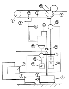
Procédé d'évacuation de l'eau de la section toile et/ou presse d'une machine à papier, selon lequel au moins un tuyau d'aspiration (1) est pourvu d'au moins un orifice (2), et raccordé à un dispositif à vide (4) servant à faire le vide au moins dans ce tuyau d'aspiration. En outre, selon le procédé, on fait passer sur l'orifice du tuyau d'aspiration un feutre, une toile ou analogue, l'eau étant de ce fait évacuée du feutre, de la toile ou analogue. Selon ledit procédé, on règle le degré de dépression en mesurant et/ou en réglant au moins la quantité d'eau évacuée par le tuyau d'aspiration (1) et, en fonction des données mesurées, on règle le degré de dépression à l'aide de dispositifs de régulation (11, 12). On a également prévu un appareil de réglage du degré de dépression.


Abrégé anglais


Paper drainage and drying is required in modern high
speed paper machines where the number of suction boxes is
limited. The present method provides a procedure for the
drainage of the wire and/or press section of a paper
machine, in which procedure at least one gap and the
suction pipe is connected to a vacuum device to develop a
vacuum at least in this vacuum pipe, and in which
procedure a felt, wire or equivalent is moved over the
gap of the suction pipe, water being thus drained from
the felt, wire or equivalent. In the procedure, the
vacuum capacity is adjusted by measuring and/or adjusting
at least the amount of water drained from the suction
pipe and, on the basis of the measured data, adjusting
the vacuum capacity by means of regulating devices. The
invention also relates to an apparatus for adjusting the
vacuum capacity.

Revendications

Note : Les revendications sont présentées dans la langue officielle dans laquelle elles ont été soumises.


5


CLAIMS

1. A method for draining an amount of water from the
wire and/or press section of a paper machine including a
carrier for a wet web of paper, at least one roller over
which the carrier passes, at least one suction pipe
having at least one inlet adjacent the carrier, and a
vacuum device, having a vacuum capacity, connected to the
suction pipe for developing a vacuum in the suction pipe,
the method comprising the steps of:
draining a first amount of water from the web
carrier through the suction pipe;
determining first data representative of the first
amount of water drained;
draining by centrifugal force a second amount of
water from said roller into a collecting element;
determining second data representative of the second
amount of water drained; and
adjusting the vacuum capacity based on the first and
second data so as to control overall drainage from the
machine.
2. The method of claim T wherein the adjusting step
comprises, at least in part, adjusting the vacuum
capacity in the suction pipe by adjusting at least one
valve element disposed between the suction pipe and the
vacuum device of the paper machine.
3. The method of claim 1 wherein the adjusting step
comprises periodically operating the vacuum device.


6


4. The method of claim 1 wherein the adjusting step
comprises adjusting the rotational speed of the vacuum
device.
5. The method of claim 1 wherein the adjusting step
comprises varying the rotational speed of a centrifugal
fan disposed below the suction pipe.
5. The method of claim 1 wherein the adjusting step
comprises adjusting the vacuum capacity according to
preprogrammed data.
7. The method of claim 6 wherein said preprogrammed
data is based on a drainage ratio between water drained
through the suction pipe and water drained into the
collecting element, the ratio being adjustable by manual
or automatic means.
8. The method of claim 1 wherein the adjusting step
comprises adjusting the vacuum capacity by use of a
control unit.
9. The method of claim 1 wherein the adjusting step
comprises varying the position of the static vanes of a
centrifugal fan on the suction and pressure sides of said
fan.
10. An apparatus for draining the wire and/or press
section of a paper machine, comprising:
a wet paper web carrier;
at least one roller over which the carrier passes;
at least one suction pipe having at least one inlet
over which the carrier passes;


7


a water collecting element disposed below the
roller;
at least one vacuum device, having a vacuum
capacity, connected to the suction pipe by one or more
pipe elements;
means for moving the web carrier over the inlet of
the suction pipe for drying a paper web carried by the
carrier;
means connected to said pipe elements for
determining first data representative of an amount of
water drained from the suction pipe;
means connected to said collecting element for
determining second data representative of an amount of
water flowing from the collector element; and
means connected to said vacuum-device for adjusting
the vacuum capacity of the vacuum device, based on the
first and second data.
11. The apparatus of claim 10 wherein the adjusting
means comprises regulating devices.
12. The apparatus of claim 11 wherein the regulating
devices comprise a control unit and at least one valve
element.
13. The apparatus of claim 12 wherein the valve element
comprises at least one throttle valve and/or a
replacement air valve.

Description

Note : Les descriptions sont présentées dans la langue officielle dans laquelle elles ont été soumises.


CA 02201513 2005-06-03
1
PROCEDURE AND APPARATUS FOR THE DRAINAGE OF THE WIRE AND/OR
PRESS SECTION OF A PAPER MACHINE OR EQUIVALENT
The present invention relates to a procedure and to an
apparatus for the drainage of the wire and/or press section
of a paper machine.
In the paper industry, drainage is implemented using suction
pipes, suction boxes, suction rollers or equivalent provided
with longitudinal gaps or holes against a wire screen, felt
or equivalent. Each suction pipe i~~ so placed that the
wire, felt or equivalent passes over the gap or holes and
drying is effected as the water is hurled by a centrifugal
force into the roller trough. The water is gathered in the
suction pipe and passed to a suitable collecting place. An
apparatus of this type is presented in. US Patent 4,329,201.
In current systems, the vacuum is adjusted on the basis of
pressure, by using various valve elements or by varying the
rotational speed of a pump unit to maintain a desired
pressure. Of the processes in a paper machine, the vacuum
system is responsible for the highest power consumption. It
also has an effect on the driving output and steam
consumption of the press and wire section. In the solutions
currently used, the adjustment of the vacuum capacity
affects the negative pressure, but it has not been possible
to reliably determine the effect of t:he adjustment on the
drainage of the paper machine. An excessively high vacuum
level is not beneficial to drainage. Instead, it increases
the pumping costs and the costs resull~ing from the wear of
fabrics and consumption of energy caused by increased
friction.
The object of the present invention is to achieve a
completely new solution that allows the: drawbacks of known


WO 96/12064 PCTIFI95/00521
2
technology to be avoided.
The invention is based on an idea according to which the
vacuum capacity is adjusted on the basis of water volume
measurements with the aid of preprogrammed data. More
particularly, the invention is characterized by what is
presented in the claims.
The solution of- the invention has numerous significant
advantages. It makes it possible to control the drainage of
a paper machine so that an optimal drainage situation is
reached, with the result that the solids content e.g. after
the press section is maximized. Therefore, maximal drainage
for the wire and felt type in use is achieved. The
runnability of the paper machine is improved. An adjustable
vacuum system allows considerable savings to be made in
energy consumption and has advantageous effects on paper
quality.
In the following, the invention is described by referring
to the attached drawing, which is a diagrammatic
representation of an apparatus as provided by the
invention.
The figure shows a simplified form of an apparatus for the
drainage of the wire and/or press section of a paper
machine. The apparatus comprises at least one suction pipe
1 having at least one gap 2 over which the felt, wire or
equivalent 3 passes, vacuum elements 4, piping elements 5,
6 connecting the suction pipe 1 to the vacuum elements 4,
drive elements 7, 8 for operating the vacuum devices 4 and
creating a vacuum in the suction pipe, and elements 9, 10
for moving the felt, wire or equivalent over the suction
pipe, thereby developing a vacuum for the drying of the
felt, wire or equivalent. The apparatus is provided with


WO 96/12064 ~ ~ ~ '~ 5 '~ PCT/FI95/00521
3
regulating elements 11, 12 for the adjustment of the vacuum
capacity and elements 13 at least in the suction~pipe for
the measurement and/or adjustment of the amount of water
drained, on the basis of which the vacuum capacity is
adjusted by means of the regulating elements.
'Vacuum capacity' refers to a value which equals negative
pressure (p) * pump yield value (Q).
The suction pipe 1 is placed in the apparatus in a manner
known in itself and it has a gap 2 that opens towards the
felt, wire or equivalent 3 passing over it. Connected to
the suction pipe 1 is a pipe 5 whose one end communicates
with the hollow space of a separator 16. From the lower end
IS of the separator, a pipe 18 extends downwards to a
container 17. The water flows in the pipe 18 under the
influence of gravity. Alternatively, a centrifugal pump
(not shown) can be mounted in conjunction with the pipe 18,
constituting a so-called extraction pump system. A pipe 6
starting from the upper end of the separator is connected
at its other end to the vacuum element 4, preferably a
vacuum pump. The pump 4 is operated by means of the drive
elements 7, 8.
The regulating elements consist of a control unit 12 and at
least one valve element 11. The control unit 12 is
preferably a process computer or equivalent. The valve
element 11 preferably consists of at least one throttle
valve and/or a replacement air valve. The valve element 11
is placed in the piping between the suction pipe 1 and the
" vacuum device 4 preferably near the suction pipe, most
preferably in the pipe 6 between the pump 4 and the
separator 16.
The apparatus comprises a collecting element 15, preferably


WU 96112064 PCT/FI95I00521
4
a so-called nip water trough, into which the water is
hurled by a centrifugal force.
The apparatus is provided with measuring devices 13 for the
measurement of the amount of water drained. The measuring
element that measures the amount of water drained from the
suction pipe 1 is preferably placed in pipe 18 between the
collecting element 15 and the container 19 or the like.
The control unit 12 may consist e.g. of a process computer
connected to receive the data supplied by the water meters
13, 14 and to adjust the vacuum capacity on the basis of
these data. The adjustment of the vacuum capacity is
controlled on the basis of information adjusted according
to the water measurements or on the basis of preprogrammed
information. The control unit preferably regulates the
valve element 11 and/or the drive 7 of the pump 4. The
vacuum capacity is adjusted in the suction piping by means
of .the valve element 11 and/or periodic operation of the
pump 4 and/or by adjusting the speed of rotation of the
vacuum pump 4 and/or by varying the rotational speed of the
centrifugal fan or the position of the static vanes on its
suction and pressure sides. With the solution of the
invention, the ratio of the amounts of water drained from
the suction pipe 1 and the collecting element 15 can be
adjusted or programmed.
It is obvious to the person skilled in the art that the
invention is not restricted to the application example
described above, but that it may instead be varied within
the scope of the following claims.

Dessin représentatif
Une figure unique qui représente un dessin illustrant l'invention.
États administratifs

Pour une meilleure compréhension de l'état de la demande ou brevet qui figure sur cette page, la rubrique Mise en garde , et les descriptions de Brevet , États administratifs , Taxes périodiques et Historique des paiements devraient être consultées.

États administratifs

Titre Date
Date de délivrance prévu 2007-01-30
(86) Date de dépôt PCT 1995-09-22
(87) Date de publication PCT 1996-04-25
(85) Entrée nationale 1997-04-01
Requête d'examen 2001-12-14
(45) Délivré 2007-01-30
Expiré 2015-09-22

Historique d'abandonnement

Il n'y a pas d'historique d'abandonnement

Historique des paiements

Type de taxes Anniversaire Échéance Montant payé Date payée
Enregistrement de documents 100,00 $ 1997-04-01
Le dépôt d'une demande de brevet 150,00 $ 1997-04-01
Taxe de maintien en état - Demande - nouvelle loi 2 1997-09-22 50,00 $ 1997-07-21
Taxe de maintien en état - Demande - nouvelle loi 3 1998-09-22 50,00 $ 1998-08-14
Taxe de maintien en état - Demande - nouvelle loi 4 1999-09-22 50,00 $ 1999-08-12
Taxe de maintien en état - Demande - nouvelle loi 5 2000-09-22 75,00 $ 2000-07-24
Taxe de maintien en état - Demande - nouvelle loi 6 2001-09-24 75,00 $ 2001-08-02
Requête d'examen 200,00 $ 2001-12-14
Taxe de maintien en état - Demande - nouvelle loi 7 2002-09-23 75,00 $ 2002-07-22
Taxe de maintien en état - Demande - nouvelle loi 8 2003-09-22 150,00 $ 2003-09-08
Taxe de maintien en état - Demande - nouvelle loi 9 2004-09-22 200,00 $ 2004-08-27
Taxe de maintien en état - Demande - nouvelle loi 10 2005-09-22 250,00 $ 2005-08-26
Taxe de maintien en état - Demande - nouvelle loi 11 2006-09-22 250,00 $ 2006-08-23
Taxe finale 300,00 $ 2006-11-14
Expiré 2019 - Paiement rectificatif/L'article 78.6 725,00 $ 2006-12-19
Taxe de maintien en état - brevet - nouvelle loi 12 2007-09-24 250,00 $ 2007-08-23
Taxe de maintien en état - brevet - nouvelle loi 13 2008-09-22 250,00 $ 2008-08-25
Taxe de maintien en état - brevet - nouvelle loi 14 2009-09-22 250,00 $ 2009-09-10
Taxe de maintien en état - brevet - nouvelle loi 15 2010-09-22 450,00 $ 2010-09-09
Taxe de maintien en état - brevet - nouvelle loi 16 2011-09-22 450,00 $ 2011-09-08
Taxe de maintien en état - brevet - nouvelle loi 17 2012-09-24 450,00 $ 2012-09-07
Taxe de maintien en état - brevet - nouvelle loi 18 2013-09-23 450,00 $ 2013-09-09
Taxe de maintien en état - brevet - nouvelle loi 19 2014-09-22 450,00 $ 2014-09-05
Titulaires au dossier

Les titulaires actuels et antérieures au dossier sont affichés en ordre alphabétique.

Titulaires actuels au dossier
ECOPUMP OY
Titulaires antérieures au dossier
KARVINEN, JUHA
Les propriétaires antérieurs qui ne figurent pas dans la liste des « Propriétaires au dossier » apparaîtront dans d'autres documents au dossier.
Documents

Pour visionner les fichiers sélectionnés, entrer le code reCAPTCHA :


Pour visualiser une image, cliquer sur un lien dans la colonne description du document. Pour télécharger l'image (les images), cliquer l'une ou plusieurs cases à cocher dans la première colonne et ensuite cliquer sur le bouton "Télécharger sélection en format PDF (archive Zip)" ou le bouton "Télécharger sélection (en un fichier PDF fusionné)".

Liste des documents de brevet publiés et non publiés sur la BDBC .

Si vous avez des difficultés à accéder au contenu, veuillez communiquer avec le Centre de services à la clientèle au 1-866-997-1936, ou envoyer un courriel au Centre de service à la clientèle de l'OPIC.


Description du
Document 
Date
(yyyy-mm-dd) 
Nombre de pages   Taille de l'image (Ko) 
Dessins représentatifs 2006-05-11 1 7
Abrégé 1997-04-01 1 53
Dessins représentatifs 1997-07-02 1 3
Description 1997-04-01 4 176
Revendications 1997-04-01 2 83
Dessins 1997-04-01 1 13
Page couverture 1997-07-02 1 47
Abrégé 2005-06-03 1 33
Description 2005-06-03 4 184
Revendications 2005-06-03 3 112
Page couverture 2007-01-04 2 46
Cession 1997-04-01 3 118
PCT 1997-04-01 7 265
Correspondance 1997-04-29 1 39
Cession 1997-04-14 2 46
Cession 1997-06-05 1 20
Poursuite-Amendment 2001-12-14 1 27
Poursuite-Amendment 2002-02-14 1 32
Taxes 2003-09-08 1 35
Taxes 1999-08-12 1 28
Taxes 1997-07-21 1 34
Taxes 1998-08-14 1 34
Taxes 2001-08-02 1 24
Taxes 2002-07-22 1 44
Taxes 2000-07-24 1 29
Poursuite-Amendment 2004-12-20 3 104
Poursuite-Amendment 2005-06-03 9 407
Correspondance 2006-11-14 2 48
Poursuite-Amendment 2006-12-19 2 76
Correspondance 2007-01-04 1 15