Note: Descriptions are shown in the official language in which they were submitted.
3~05~1997 12:59 CA 02205928 1997-05-23 02
.
A D~rr~U~ JU~r IN ~ 3A~ ~JD IUN ~U~ U~
A~ ~n~ ~ A5 ~ ~o~ ~ OD POR ,~r~u~INa ~ne ~AJC~
The lnvention relate~ to a llnk according to ~he lntroductory cln~ of
clalm 1.
When jolnl~g ~rtiflclal ceeth, ~uch a~ a tooth bridye, to a jaw implane, a
problem consl~t~ ln that that the ~aw ~ighe have grown und~r an angle to a
horl~ont~ plane not con~ ent wit~ the angle of the tee~. Therefore, a
llnk is nece~ary by whlch the dif~erence of anyle~ i~ compensaeed. In the
pa~e, it ha~ been round that adaptatlon 1~ difficul~ due to very dl~ferent
angle~ of difforent patient~. Cer~ainly, one ha~ eried to ~orm a head
1~ portlon a~ an a~atment ball eo whlch a tooth ~leeve ~orming a hollo~
~phere i~ clampod. It ~hould be noted, howe~er, that the forceB oCcurring
o~ ~ ~aw are -very high for which rea~on the clamped tooth ~leeve may
ea~lly become loo~e again. ~xample~ of ~uch adju~tmen~ facllltleJ can be
derlved ~rom US-A-5,092,770 a~ well a~ the U~-A-5,417,570 and -5,4g3,~67
20 publl~hed wlthln ehe priority interval. The WO 93/0972~ de~cribe~ a llnk
comprlslng ~wo ~crew bolts, a sleeve being ~crewed on~o the ~e~ond one to
clamp the ball of an orieneable bol~.
There~ore, ie 1~ an ob~ect of the inv~nt$on to con~truct a llnk o~ the
2S klnd mentioned in tho out~et in a toug~ and ~lmple manner, taking into
account, nevertheless, the indivldual angular po~ltlon of a jaw l~plan~
and the tooth~ an~le. Thi~ i~ achle~ed by meane of a link compris~n~ the
characeerizing ~eature~ Or cl~lm 1.
Du~ to the ~act that both s~rew bolt~, thus, will form an lneegral ~art of
a unit, ~u~equent ad~u~ement and clamplng becomeR unnece~ary ~o that a
tough and ~trong ~onetruction i~ warranted. The individual angular
po~ltion Or ~aw implunt ~d tooth's angle ie con~ldered, chereby, by
formtng the two ~crew bolt~ under ehe respeceive an~le.
3~
Theoretically, thi~ would be poe~i~lo by mea~urlng the angle and
reprodu~lng tha~ in the two bolte, euch a~ by a caeeing
CA 0220~928 1997-0~-23
process or another shaping process. Advantageous is, how-
ever, the manufacture of the link according to the invention
by the steps indicated in claim 4 as well in its sub-claims,
particularly in an embodiment according to claim 5
In order to avoid problems with placing a machining tool
under an angle to a first screw bolt, preferably the cha-
racteristics o~ claim 6 are provided. The curved sur~ace may
have any shape, e.g. an oval shape, if it facilitates only
handling of the mach~n;ng tool. It is preferred, however, if
the curved shape forms a ball. This will then result in an
embodiment of the link in accordance with claim 2. Thus, the
ball does not have an adjustment function, as it was the
case with the prior art, but serves, as already mentioned, a
facilitated placement or handling of the tool.
Further details of the invention will become apparent from
the following description of an embodiment schematically
illustrated in the drawings wherein:
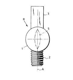
Fig. l is a blank according to the invention for
producing a link according to the invention;
Fig. lA is a front view of a pin indicating and mar-
king the position and orientation of a screw
bolt on the blank;
Fig. 2 illustrates putting a hollow cutter tool onto
a head portion of the blank after having made
a jaw mold for determining the position of
the axis of the implant and of the bolt of
the blank to be screwed in, and after having
removed the marking pin for indicating the
orientation of the axis of the bolt;
Fig. 2A a view ~rom below onto the machining surface
of the hollow cutter tool;
CA 0220~928 1997-0~-23
~ig. 3 shows the link provided with another bolt,
having a threaded sleeve screwed on for hol-
ding an arti~icial tooth, and being in a
position when screwed into the implant
In order to produce a link between a dental implant 4 (see
Fig. 3) in a jaw and an artificial tooth, Such as a tooth
bridge, one starts with a blank R according to Figs. 1 and
lA. This blank R consists of a ~irst screw bolt 2 for fas~
tening onto the dental implant 4, and a head portion 1. For
reasons which will become apparent later, this head portion
1 is suitably rounded and is, in particular, spherical, as
may be seen from Fig. 1.
When an implant has been inserted into a jaw of a patient, a
blank R according to Fig. 1 is screwed on by means o~ the
screw bolt 2 and is tightened. A~ter this, a jaw mold is
made by a rubber-like mass in a known manner.
Especially in the pre~erred embodiment where the head por-
tion 1 spherical, the position and orientation of the screw
bolt 2 and its axis A could subsequently not be recognized
by means of the mold, because only the head portion 1 pro-
trudes from the implant. If the head portion were, however,
elongated and had a longitudinal axis in continuation o~ the
axis A, this would indicate the orientation and angular po-
sition. On the other hand, this would make later machining
more di~ficult.
Therefore, it is preferred if an arrangement for marking the
orientation of axis A within the jaw and the implant is pro-
vided. This marking arrangement might be formed as a notch 5
(indicated in dash-dotted lines) in the spherical surface of
head portion 1, although this is not preferred. It is more
favorable to indicate the orientation of the axis A by a
projection 3 extending in alignment with the axis A. Such a
pin-like or semi-cylindrical projection 3 gives an unequi-
vocal trace or indention within the rubber mold and, there-
CA 0220~928 1997-0~-23
fore, provides a clear indication of the position of the
blank and the orientation o~ the axis A. The pin-like pro-
jection has to be formed in such a manner that it can be in-
serted in a single orientation into the recesses caused by
itself in the mold.
After removing the mold, the respective blanks R are screwed
off again, numbered l to x and are sent to a dental labora-
tory. There, they can each be screwed and tightened by means
of the screw bolt 2 in manipulation implants. Then, their
semi-cylindrical projections are inserted into the corres-
ponding recesses of the rubber mold so that all threads of
the screw bolt 2 have the same orientation relative to the
mold aS they had during taking the mold from the jaw of the
patient when they were completely screwed in. Then, the
space up to just beneath the blank and its head l is filled
up with a hardening mass, such as gypsum, in order to fix
the position of the blank and the orientation of the axis A
of the screw bolt 2 which was previously determined by means
of the pin 3, and which corresponds to the position of the
implant within the jaw of the respective patient.
This situation is represented in Fig. 2 where a dash-dotted
line G indicates the level of the gypsum bed. For the sake
of simplicity, the manipulation implant of the laboratory is
omitted in Fig. 2. Moreover, the marking pin 3 was sawed
off. which is no longer necessary after removal of the mold,
so that a smooth ball presents its surface. It may be seen
that smoothness would be affected if the notch 5 were used
to mark the orientation of the axis A.
If, in this situation, a mach;n-ng tool, such as the hollow
cutter tool 6 shown in Figs. 2 and 2A, is lowered along a
precisely vertical axis S onto the ball l, it will cut a
further bolt 7 out of the ball l which can then be provided
with a thread, as may be seen from Fig. 3. The bolt 7 will
then extend precisely along the axis S, and this will inter-
sect with the axis A in the center point o~ the ball, the
CA 0220~928 1997-0~-23
S
.
two axes A, S ~orming an angle with each other which is de-
termined by the position of the implant 4 within the jaw of
the patient, on the one hand, and by the desired orthogonal
position o~ the respective artificial tooth, on the other
hand.
To this end, the hollow cutter 6 has both frontal mach;n;ng
edges 8 and inner mach;n;ng edges 9 ~orming a hollow cylin-
der. The result o~ such machining may be seen from Fig. 3
where the finished link B is represented as being already
inserted into the implant 4 o~ the patient. A~ter tightening
the screw bolt 2 in the implant of the jaw, the two screw
bolts 2 and 7 are in a fixed, and therefore immovable, but
also correct angular orientation ensured by the previously
discussed steps. From foregoing mach;~;ng, this link B has
still a portion l' in the form of a ball segment, a ball
sur~ace l" ~acing the ~irst screw bolt, while the other
screw bolt 7 has a length which corresponds to more than
half, e.g. 2/3 of the whole spherical surface (c~. Figs. l,
2) which ~orms also the ball sur~ace l". It may be conve-
nient that the two bolts 2, 7 have opposite threads, e.g. to
provide a le~t-handed thread on bolt 7.
~nto this screw bolt 7, a nut or tooth sleeve lO may be
~5 screwed on that is attached to the respective arti~icial
tooth, such as the above-mentioned bridge, and which has an
edged cross-section, e.g. a squared one or, pre~erably, a
hexagonal one, ~or better handling it at the end having the
opening. The bridge is then, for example, cemented onto this
nut sleeve. By aligning all axes S o~ blanks o~ a mold pa-
rallel to each other after mach;nlng to ~orm links, an ar-
ti~icial tooth having corresponding bores may be put over
them without any problem.
In addition, by having and end portion of the nut sleeve lO
which ~aces the jaw and comprises an edged cross-section
enables also easier detaching in case it is necessary. It
would then be engaged by a screw spanner and turned with re-
CA 0220~928 1997-0~-23
spect to the thread of the bolt 7. The high torque which can
be attained enables release of the connection or cemented
connection between the tooth sleeve or nut sleeve and the
artificial tooth. After releasing all sleeves, the bridge
has merely to be lifted. On the other hand, the method ac-
cording to the invention enables a joint to be established
under various angles of inclination with respect to a ver-
tical plane in a simple and tough manner where attaching and
detaching present no problem.
By carefully carrying out the method described, it will be
ensured that the threads of the manipulation implants are
arranged within the gypsum mold in an identical manner with
those threads of the implants fastened to the jaw. There-
fore, the further bolt or screw bolt 7 of blank in the gyp-
sum mold will be oriented in the desired direction after
having completely screwed the link B into an implant in the
jaw. If, for example, a damaged link had to be replaced
later, a new one can be produced from a new blank directly
in a gypsum mold. After releasing the tooth sleeves and lif-
ting the artificial tooth, the damaged link is screwed out
o~ the implant and is replaced by a new one. Then, the tooth
sleeve and the artificial tooth may be put on it immediately
again.