Note: Descriptions are shown in the official language in which they were submitted.
CA 02228106 1998-01-28
BACKGROUND OF THE INVENTION AND PRIOR ART
The invention relates to an impact member for an impact crusher comprising a
rotor and an impact member provided in the housing in an adjustable position,
directly underneath the feed aperture for the material to be crushed.
An impact crusher is known from DE 44 40 076 C1 the impact member of which,
provided directly underneath the entry to the housing, is mounted pivotally
around a horizontal axis.
Such impact members are structurally complex and prone to faulty operation.
GENERAL DESCRIPTION OF THE INVENTION
The applicants have recognized a need for an impact member of the type as set
out in the opening paragraph which is of simple design and operationally
reliable.
The present invention provides an impact member as set out in the opening
paragraph which is an impact plate linearly displaceable in relation to the rotor.
It is an important feature of the invention that the impact member arranged
directly underneath the entry to the housing, is arranged linearly displaceable in
relation to the rotor via drive mechanisms, for example hydraulic cylinders, therespective gap width of the crushing gap being ensured by the provision of a
pre-determined number of spacer discs on support plates.
A further irnportant feature of the present invention resides in that the impactplate, brought into its working position by means of spacer discs, is firmly
CA 02228106 1998-01-28
pressed onto the support flanges by hydraulic pressure cylinders. This ensures
that the function of the impact member is ensured in all circumstances and that
no damaging foreign-object material can enter between these two installation
parts, ensuring therefore a troublefree displacement function of the impact
plates.
Each one of the pressure cylinders projecting into the crushing chamber and
present in variable numbers, is further protected against damage and dust by a
protective cap.
This linearly displaceable impact plate according to the invention for impact
crushers is characterized, in particular, by low production costs, in addition, it is
easy to ernploy, moreover, it allows short retooling periods and furthermore
ensures a troublefree crushing operation.
The subject of the present invention is apparent not only from the contents of the
individual claims but also from the combination of the individual claims with one
another. All information and characteristics disclosed in the documents, in
particular the design illustrated in the drawings, are claimed as essential aspects
of the invention to the extent that they are novel individually or in combination
with one another when compared with the state of the art.
In this context further important characteristics and advantages of the invention
are apparent from the following drawings and their description.
CA 02228106 1998-01-28
-
BRIEF DESCRIPTION OF THE DRAWINGS
There are shown in:
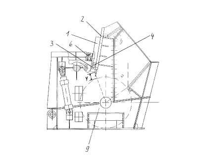
Fig. 1 a cross-section of the impact crusher including the impact plate
arrangement,
Fig. 2 a section on a larger scale of the hydraulically activatable impact
plate support flange/spacer disc arrangement according to Fig. 1,
Fig. 3 a section A-A across the impact plate-support flange arrangement
corresponding to the section line A of Fig. 2,
Fig. 4 impact crusher housing comprising an impact plate drive
mechanism and a spacer disc arrangement.
DETAILED DESCRIPTION OF SPECIFIC EMBODIMENTS OF THE INVENTION
The impact crusher shown in Fig. 1 comprises a rotor 9 adapted to be
rotationally-driven, mounted in a housing and usually equipped with crushing
elements - not shown in the drawing -, the first impact member being provided
on support flanges 2 above the said rotor, directly underneath the entry to the
housing, comprising the impact plate 1 linearly displaceable in relation to the
rotor 9, forming a crushing gap with a stepwise adjustable gap width y for
crushing large sized components of the material to be crushed. In Fig. 1 the
crusher plate 1 is illustrated in the clamped position, i.e. with spacer discs 4provided on a support plate 3 and with hydraulic pressure cylinders 6 in workingposition.
Figs. 2 and 3 in different views illustrate the impact plate 1 resting on the support
flange 2 according to Fig. 1 including the hydraulic cylinders 8 bringing about
CA 02228106 1998-01-28
the linear displacement in relation to the rotor 9, not shown here, and including
spacer discs 4 with a handle 5 mounted on support plates 3. The clamping
position is brought about by the associated hydraulic pressure cylinders 6. The
fixation of the hydraulic cylinders 8 to the housing and the impact plate 1 is also
apparent from Fig. 3.
Fig. 4 schematically shows the example of an arrangement of the hydraulic
pressure cylinders 6 and the hydraulic cylinder 8 on the housing and the impact
plate 1 comprising the arrangement of the support plate 3 and the spacer discs
4. From this Fig. 4 it is furthermore apparent that each of the hydraulic pressure
cylinders 6 projecting into the crushing chamber of the impact crusher comprisesa protective cap 7 protecting the pressure cylinder 6 against damage and dust.
The incremental linear displacement of the impact plate 1 in relation to the rotor
9, forming a stepwise adjustable crushing gap, takes place by releasing the
hydraulic pressure cylinder 6 and by raising the impact plate by means of the
hydraulic cylinders 8 with subsequent fitting or removing of spacer discs 4 by
means of their respective handle 5 and by subsequent lowering of the impact
plate 1 as well as clamping of the latter by means of the hydraulic pressure
cylinder 6.
The claims which follow are to be considered an integral part of the present
disclosure. Reference numbers (directed to the drawings) shown in the claims
serve to facilitate the correlation of integers of the claims with illustrated features
of the preferred embodiment(s), but are not intended to restrict in any way the
language of the claims to what is shown in the drawings, unless the contrary is
clearly apparent from the context.
What we claim is:
