Sélection de la langue

Search

Sommaire du brevet 2228106 

Énoncé de désistement de responsabilité concernant l'information provenant de tiers

Une partie des informations de ce site Web a été fournie par des sources externes. Le gouvernement du Canada n'assume aucune responsabilité concernant la précision, l'actualité ou la fiabilité des informations fournies par les sources externes. Les utilisateurs qui désirent employer cette information devraient consulter directement la source des informations. Le contenu fourni par les sources externes n'est pas assujetti aux exigences sur les langues officielles, la protection des renseignements personnels et l'accessibilité.

Disponibilité de l'Abrégé et des Revendications

L'apparition de différences dans le texte et l'image des Revendications et de l'Abrégé dépend du moment auquel le document est publié. Les textes des Revendications et de l'Abrégé sont affichés :

  • lorsque la demande peut être examinée par le public;
  • lorsque le brevet est émis (délivrance).
(12) Demande de brevet: (11) CA 2228106
(54) Titre français: ELEMENT D'IMPACT
(54) Titre anglais: IMPACT MEMBER
Statut: Morte
Données bibliographiques
(51) Classification internationale des brevets (CIB):
  • B02C 13/04 (2006.01)
  • B02C 13/09 (2006.01)
  • B02C 13/26 (2006.01)
(72) Inventeurs :
  • FOLLING, KLAUS (Allemagne)
  • KROKOR, WERNER (Allemagne)
(73) Titulaires :
  • KRUPP FORDERTECHNIK GMBH (Allemagne)
(71) Demandeurs :
  • KRUPP FORDERTECHNIK GMBH (Allemagne)
(74) Agent: FETHERSTONHAUGH & CO.
(74) Co-agent:
(45) Délivré:
(22) Date de dépôt: 1998-01-28
(41) Mise à la disponibilité du public: 1998-07-31
Licence disponible: S.O.
(25) Langue des documents déposés: Anglais

Traité de coopération en matière de brevets (PCT): Non

(30) Données de priorité de la demande:
Numéro de la demande Pays / territoire Date
297 01 622.9 Allemagne 1997-01-31

Abrégés

Abrégé français

L'invention concerne la façon de concevoir le déplacement de l'alignement de l'élément d'impact, dont la structure est simple et le fonctionnement fiable, d'un concasseur à impact. Ce dernier comporte un rotor (9) et un élément d'impact prévu dans le boîtier dans une position réglable se trouvant directement sous l'ouverture d'alimentation de la matière à concasser. L'élément d'impact comprend une plaque d'impact (1) se déplaçant linéairement relativement au rotor (9).


Abrégé anglais


In order to design the positional displacement of the impact member structurallysimple and operationally reliable in an impact crusher comprising a rotor (9) and
an impact member provided in the housing in an adjustable position directly
underneath the feed aperture of the material to be crushed, the impact member
is provided with an impact plate (1) linearly displaceable in relation to the rotor
(9).

Revendications

Note : Les revendications sont présentées dans la langue officielle dans laquelle elles ont été soumises.


Claims

1. Impact member for an impact crusher comprising a rotor and an impact
member provided in the housing in an adjustable position directly
underneath the feed aperture for the material to be crushed, which impact
member is an impact plate (1) linearly displaceable in relation to the rotor
(9).

2. Impact member according to claim 1, wherein the impact plate (1) rests on
lateral support flanges (2) of the crusher housing and is linearly
displaceable by hydraulic cylinders (8) in relation to the rotor (9) mounted
in a manner to be driven.

3. Impact member according to claim 1 or 2, wherein for the incremental
adjustment of the gap width (y) between the linearly displaceable impact
plate (1) and the rotor (9) a variable number of spacer discs (4), each
equipped with a handle (5), is provided on support plates (3) fitted to the
housing.

4. Impact member according to claim 1, wherein hydraulic pressure
cylinders (6) are provided for clamping the impact plate (1) firmly onto the
support flanges (2).

5. Impact member according to claim 4, wherein each pressure cylinder (6)
comprises a protective cap (7).

6. Impact crusher comprising a rotor and an impact member provided in the
housing in an adjustable position underneath the feed aperture for the
material to be crushed which impact member is an impact plate (1)
linearly displaceable in relation to the rotor (9).


Description

Note : Les descriptions sont présentées dans la langue officielle dans laquelle elles ont été soumises.


CA 02228106 1998-01-28


BACKGROUND OF THE INVENTION AND PRIOR ART

The invention relates to an impact member for an impact crusher comprising a
rotor and an impact member provided in the housing in an adjustable position,
directly underneath the feed aperture for the material to be crushed.

An impact crusher is known from DE 44 40 076 C1 the impact member of which,
provided directly underneath the entry to the housing, is mounted pivotally
around a horizontal axis.

Such impact members are structurally complex and prone to faulty operation.

GENERAL DESCRIPTION OF THE INVENTION

The applicants have recognized a need for an impact member of the type as set
out in the opening paragraph which is of simple design and operationally
reliable.

The present invention provides an impact member as set out in the opening
paragraph which is an impact plate linearly displaceable in relation to the rotor.

It is an important feature of the invention that the impact member arranged
directly underneath the entry to the housing, is arranged linearly displaceable in
relation to the rotor via drive mechanisms, for example hydraulic cylinders, therespective gap width of the crushing gap being ensured by the provision of a
pre-determined number of spacer discs on support plates.

A further irnportant feature of the present invention resides in that the impactplate, brought into its working position by means of spacer discs, is firmly

CA 02228106 1998-01-28


pressed onto the support flanges by hydraulic pressure cylinders. This ensures
that the function of the impact member is ensured in all circumstances and that
no damaging foreign-object material can enter between these two installation
parts, ensuring therefore a troublefree displacement function of the impact
plates.

Each one of the pressure cylinders projecting into the crushing chamber and
present in variable numbers, is further protected against damage and dust by a
protective cap.

This linearly displaceable impact plate according to the invention for impact
crushers is characterized, in particular, by low production costs, in addition, it is
easy to ernploy, moreover, it allows short retooling periods and furthermore
ensures a troublefree crushing operation.

The subject of the present invention is apparent not only from the contents of the
individual claims but also from the combination of the individual claims with one
another. All information and characteristics disclosed in the documents, in
particular the design illustrated in the drawings, are claimed as essential aspects
of the invention to the extent that they are novel individually or in combination
with one another when compared with the state of the art.

In this context further important characteristics and advantages of the invention
are apparent from the following drawings and their description.

CA 02228106 1998-01-28

-

BRIEF DESCRIPTION OF THE DRAWINGS

There are shown in:

Fig. 1 a cross-section of the impact crusher including the impact plate
arrangement,

Fig. 2 a section on a larger scale of the hydraulically activatable impact
plate support flange/spacer disc arrangement according to Fig. 1,

Fig. 3 a section A-A across the impact plate-support flange arrangement
corresponding to the section line A of Fig. 2,

Fig. 4 impact crusher housing comprising an impact plate drive
mechanism and a spacer disc arrangement.

DETAILED DESCRIPTION OF SPECIFIC EMBODIMENTS OF THE INVENTION

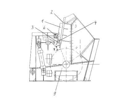
The impact crusher shown in Fig. 1 comprises a rotor 9 adapted to be
rotationally-driven, mounted in a housing and usually equipped with crushing
elements - not shown in the drawing -, the first impact member being provided
on support flanges 2 above the said rotor, directly underneath the entry to the
housing, comprising the impact plate 1 linearly displaceable in relation to the
rotor 9, forming a crushing gap with a stepwise adjustable gap width y for
crushing large sized components of the material to be crushed. In Fig. 1 the
crusher plate 1 is illustrated in the clamped position, i.e. with spacer discs 4provided on a support plate 3 and with hydraulic pressure cylinders 6 in workingposition.

Figs. 2 and 3 in different views illustrate the impact plate 1 resting on the support
flange 2 according to Fig. 1 including the hydraulic cylinders 8 bringing about


CA 02228106 1998-01-28


the linear displacement in relation to the rotor 9, not shown here, and including
spacer discs 4 with a handle 5 mounted on support plates 3. The clamping
position is brought about by the associated hydraulic pressure cylinders 6. The
fixation of the hydraulic cylinders 8 to the housing and the impact plate 1 is also
apparent from Fig. 3.

Fig. 4 schematically shows the example of an arrangement of the hydraulic
pressure cylinders 6 and the hydraulic cylinder 8 on the housing and the impact
plate 1 comprising the arrangement of the support plate 3 and the spacer discs
4. From this Fig. 4 it is furthermore apparent that each of the hydraulic pressure
cylinders 6 projecting into the crushing chamber of the impact crusher comprisesa protective cap 7 protecting the pressure cylinder 6 against damage and dust.

The incremental linear displacement of the impact plate 1 in relation to the rotor
9, forming a stepwise adjustable crushing gap, takes place by releasing the
hydraulic pressure cylinder 6 and by raising the impact plate by means of the
hydraulic cylinders 8 with subsequent fitting or removing of spacer discs 4 by
means of their respective handle 5 and by subsequent lowering of the impact
plate 1 as well as clamping of the latter by means of the hydraulic pressure
cylinder 6.

The claims which follow are to be considered an integral part of the present
disclosure. Reference numbers (directed to the drawings) shown in the claims
serve to facilitate the correlation of integers of the claims with illustrated features
of the preferred embodiment(s), but are not intended to restrict in any way the
language of the claims to what is shown in the drawings, unless the contrary is
clearly apparent from the context.

What we claim is:
Dessin représentatif
Une figure unique qui représente un dessin illustrant l'invention.
États administratifs

Pour une meilleure compréhension de l'état de la demande ou brevet qui figure sur cette page, la rubrique Mise en garde , et les descriptions de Brevet , États administratifs , Taxes périodiques et Historique des paiements devraient être consultées.

États administratifs

Titre Date
Date de délivrance prévu Non disponible
(22) Dépôt 1998-01-28
(41) Mise à la disponibilité du public 1998-07-31
Demande morte 2002-01-28

Historique d'abandonnement

Date d'abandonnement Raison Reinstatement Date
2001-01-29 Taxe périodique sur la demande impayée

Historique des paiements

Type de taxes Anniversaire Échéance Montant payé Date payée
Enregistrement de documents 100,00 $ 1998-01-28
Le dépôt d'une demande de brevet 300,00 $ 1998-01-28
Taxe de maintien en état - Demande - nouvelle loi 2 2000-01-28 100,00 $ 1999-12-23
Titulaires au dossier

Les titulaires actuels et antérieures au dossier sont affichés en ordre alphabétique.

Titulaires actuels au dossier
KRUPP FORDERTECHNIK GMBH
Titulaires antérieures au dossier
FOLLING, KLAUS
KROKOR, WERNER
Les propriétaires antérieurs qui ne figurent pas dans la liste des « Propriétaires au dossier » apparaîtront dans d'autres documents au dossier.
Documents

Pour visionner les fichiers sélectionnés, entrer le code reCAPTCHA :


Pour visualiser une image, cliquer sur un lien dans la colonne description du document. Pour télécharger l'image (les images), cliquer l'une ou plusieurs cases à cocher dans la première colonne et ensuite cliquer sur le bouton "Télécharger sélection en format PDF (archive Zip)" ou le bouton "Télécharger sélection (en un fichier PDF fusionné)".

Liste des documents de brevet publiés et non publiés sur la BDBC .

Si vous avez des difficultés à accéder au contenu, veuillez communiquer avec le Centre de services à la clientèle au 1-866-997-1936, ou envoyer un courriel au Centre de service à la clientèle de l'OPIC.


Description du
Document 
Date
(yyyy-mm-dd) 
Nombre de pages   Taille de l'image (Ko) 
Dessins représentatifs 1998-10-02 1 11
Page couverture 1998-10-02 1 39
Abrégé 1998-01-28 1 12
Description 1998-01-28 4 143
Revendications 1998-01-28 1 34
Dessins 1998-01-28 4 57
Cession 1998-01-28 4 121