Language selection

Search

Patent 2228856 Summary

Third-party information liability

Some of the information on this Web page has been provided by external sources. The Government of Canada is not responsible for the accuracy, reliability or currency of the information supplied by external sources. Users wishing to rely upon this information should consult directly with the source of the information. Content provided by external sources is not subject to official languages, privacy and accessibility requirements.

Claims and Abstract availability

Any discrepancies in the text and image of the Claims and Abstract are due to differing posting times. Text of the Claims and Abstract are posted:

  • At the time the application is open to public inspection;
  • At the time of issue of the patent (grant).
(12) Patent: (11) CA 2228856
(54) English Title: MATERIAL COLLECTION BAG
(54) French Title: SAC COLLECTEUR
Status: Deemed expired
Bibliographic Data
(51) International Patent Classification (IPC):
  • A01D 43/063 (2006.01)
  • A01D 34/63 (2006.01)
(72) Inventors :
  • HOPKINS, JOHN WILLIAM (United States of America)
  • LEASURE, JEREMY DOUGLAS (United States of America)
(73) Owners :
  • DEERE & COMPANY (United States of America)
(71) Applicants :
  • DEERE & COMPANY (United States of America)
(74) Agent: BORDEN LADNER GERVAIS LLP
(74) Associate agent:
(45) Issued: 2001-10-16
(22) Filed Date: 1998-03-09
(41) Open to Public Inspection: 1998-12-09
Examination requested: 1998-03-09
Availability of licence: N/A
(25) Language of filing: English

Patent Cooperation Treaty (PCT): No

(30) Application Priority Data:
Application No. Country/Territory Date
08/871,046 United States of America 1997-06-09

Abstracts

English Abstract


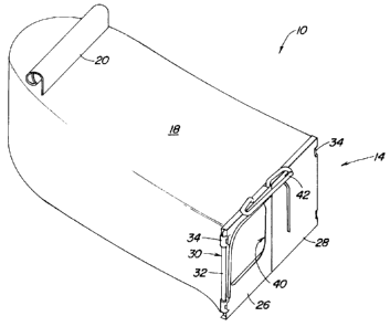
A bagger with a pair of doors at its opening is provided for a walk-behind lawn
mower. The bagger opening is provided with a rectangular metal framework with one door
being swingably attached to each spaced-apart vertical leg of the framework. The bagger
includes a rear handle for supporting its rear portion from the mower push handle and a
front handle integrally formed as part of the framework. The front handle is slidably and
removably receivable on a hook secured to the mower discharge chute for quick and easy
installation and removal. The dual doors, which swing away from one another, facilitate
easy insertion of the bagger opening and doors into or out of a refuse can or bag to permit
disposal of clippings.


French Abstract

La présente invention fait état d'un ensacheur pour tondeuse à gazon poussée par l'utilisateur. L'ouverture de l'ensacheur est constituée d'un cadre rectangulaire métallique et de deux trappes fixées, de façon à pouvoir s'ouvrir et se fermer, sur un des montants verticaux espacés du cadre. L'ensacheur est muni d'une poignée arrière, accrochée au guidon de la tondeuse pour soutenir la partie arrière de l'ensacheur, et d'une poignée avant formée à même le cadre. La poignée avant se fixe, de façon non permanente, par glissement à un crochet ancré à la goulotte d'éjection de la tondeuse, ce qui permet d'installer et d'enlever facilement et rapidement l'ensacheur. Les trappes doubles s'ouvrent en s'éloignant l'une de l'autre, ce qui permet d'introduire facilement l'ouverture et les trappes de l'ensacheur dans une poubelle ou dans un sac afin de jeter les déchets de tonte puis de retirer l'ensacheur.

Claims

Note: Claims are shown in the official language in which they were submitted.


The embodiments of the invention in which an exclusive property or privilege is
claimed are defined as follows:
1. A bagging assembly usable with a walk-behind lawn mower, the lawn mower
having a chute with an opening through which clippings can be discharged, the assembly
including a bag with an opening for receiving clippings from the chute, and a generally rigid
framework attached to the bag and surrounding the opening,
the framework including laterally spaced apart and generally vertically
extending legs;
a pair of doors, one door being attached to each vertical leg for swinging movement
about an axis extending through said leg, one door having an opening for receiving
material propelled through the chute; and
means for releasably securing the framework of the bag with the chute.
2. The invention defined in claim 1 wherein the framework is generally rectangular and
includes two spaced apart generally vertical metal legs with one door being removably
mounted on each leg for swinging movement.
3. The invention defined in claim 1 wherein the doors are made of composite material.
4. The invention defined in claim 3 wherein each door includes means permitting it to
be slidably snapped onto one leg.
5. The invention defined in claim 1 wherein each door includes a vertical edge, said
doors being swingably movable between first closed positions where their respective vertical
edges are adjacent and second open positions where their vertical edges are laterally
spaced apart.
6. The invention defined in claim 1 wherein the mower includes a push handle and the
bag assembly includes a hanger which can be removably attached to the handle.
7. The invention defined in claim 1 wherein the framework includes an upwardly and
forwardly extending handle, the chute includes an upwardly and rearwardly extending hook
and the handle is adapted to be removably supported on the hook.
8. The invention defined in claim 7 wherein the handle includes at least one slot
through which the hook can be slidably received.
9. The invention defined in claim 1 wherein each door is substantially smaller than the
opening in the bag.

Description

Note: Descriptions are shown in the official language in which they were submitted.


CA 022288~6 1998-03-09


MATERIAL COLLECTION BAG

l~ield of InvenUon:
The present invention relates to walk-behind lawn mowers and more particularly to
5 material collection bags used with such mowers.

~escri,.,tion of the related art:
Homeowners frequently collect and bag grass and other clippings generated when
lhey mow their lawns. This practice is adopted to provide a lawn having a more finished and
10 desirable appearance. If the grass clippings are not composted by the homeowner,
generally they must be placed in a refuse can or bag for disposal.
Comn-lonly, material collection bags attach to a discharge chute carried at the rear of
vvalk-behind mowers and extend rearwardly behind them. The bags include an opening at
their forward portion, which serves to receive clippings from the discharge chute and permit
15 collected clippings to be emptied.
Some bags include a door that covers the bag opening. While such doors usually
include a small opening to allow clippings to pass from the chute and into the bag, they are
often mounted to swing to an opened position to permit the bag to be emptied. When the
operator atternpts to empty such a collection bag into a refuse can or paper or plastic refuse
20 bag, the opened door often interferes with the ability to insert the bag into the container
and/or with th~e ability to empty clippings into the container.

SUMMARY OF THE INVENTION

It would therefore be desirable to provide a material collection bag with a doorassembly which would enable the bag to receive clippings during the mowing process and
contain them iin the bag when it is carried from the mower to a discharge area.
It would further be desirable to provide a door assembly that would permit the bag
c~pening and il:s door to be easily inserted into a refuse can or paper or plastic refuse bag
and emptied without having the door interfere with that process.
Towarcl these ends, there is provided a material collection bag having a door
assembly that permits the bag opening and door to be easily inserted into refuse bags or
c:ans and emptied.
The door assembly is mounted to a rigid rectangular framework carried around theperimeter of the bag opening. One door is mounted to each opposite vertical leg of the
framework for swinging movement between open and closed positions.

CA 022288C.6 1998-03-09


One dc.or is provided with an opening through which clippings can pass from the
rnower discharge chute. Both doors in the preferred embodiment are composed of
composite malterials such as plastic.
The b,3g is provided with front and rear handles, the rear handle being supported by
the mower push handle and the front handle being coupled with the rectangular framework.
The front handle is further removably receivable on a hook carried on the mower discharge
chute to quick.ly and easily secure the front of the bag to the mower chute
With the present invention, a material collection bag assembly is provided which is
cluickly and easily installed or removed from the mower and one which permits the filled bag
10 to be easily emptied into a refuse bag or can.

BRIEF DESCRIPTION OF THE DRAWINGS

F:igure 1 is a front elevated perspective of the bag and door assembly with the mower and
discharge chute illustrated in phantom.
F igure 2 is an elevated perspective view of the bag and door assembly.
F igure 3 is an elevated perspective view of door assembly.
F-igure 4 is a front view of the framework and discharge chute hook.
F igure 5 is a c,ut-away view taken along line 6 of Figure 5 illustrating the door assembly and
framework when mounted to the discharge chute.
F igure 6 is a view similar to that taken of Figure 6, showing however, the door being slidably
removcd from the discharge chute hook.

DESCRIPTION OF THE PREFERRED EMBODIMENT
Looking first to Fig. 1, there is shown a material collection bag or bagger 10 carried
at the rear of ;3 walk-behind lawn mower 12, the mower 12 being illustrated in phantom. The
bagger 10 includes a door assembly 14 which secures it to the discharge chute 16 of the
rnower 10.
Looking also to the enlarged views found in Figs. 2 and 3, it can be seen that the
bagger 10 includes a clippings container 18, which in the preferred embodiment is made of
a soft materiall such as cloth. At the rearward portion of the bagger 10, there is secured a
handle 20 for supporting the rear of the bag 10 on the mower push handle 22. At its forward
portion, the bagger 10 includes an opening 24 wherein a door assembly 14 is mounted. As
35 best seen in Fig. 3, the door assembly 14 includes two separate doors 26 and 28 which are

CA 022288~6 1998-03-09


carried on a rod like framework 30 which in is turn secured to the cloth container 18 at its
opening. The framework 30 takes the form of a rectangle and includes laterally spaced-apart
and generally vertically extending side members or legs 32. To each of the legs 32 is
attached one of the doors 26 and 28, see Figs. 3 and 4. These doors 26 and 28 are, in the
5 preferable embodiment, made of a composite material such as plastic and include portions
34 which can be slidably positioned on the vertical legs 32 and snapped into place to hold
them to the re!spective legs 32. Reinforcing ribs 36 have been provided in the preferred
embodiment.
As is also shown in Fig. 4, the doors 26 and 28 are mounted for swingable
10 rnovement about vertical axis 38 extending through the laterally spaced-apart vertical legs
'32 to permit them to open as shown in Fig. 3 or be moved to their closed position as
illlustrated in Fig. 2. The left door 26 includes an opening 40 through which material can be
received from the discharge chute 16.
The fnamework 30 includes a front handle 42 which is integrally formed into it. The
front and rear handles 42 and 20 support the bagger 10 on the lawn mower 12 and provide
ready handgrips for the operator to remove the bagger 10 from the lawn mower 12 and
c:arry it to a se!parate location for disposal of the clippings.
Looking now to Figs. 4, 5, and 6, the framework 30 with its handle 42 and the chute
rod 44 and support hook 46 are illustrated. The handle 42 includes two slotted areas 48
formed to fit around and slide along the hooked portion 46 of the rod 44 secured to the
c:hute 16. As can be seen in Figs. 5 and 6, the hook 46 projects upwardly and rearwardly.
In operation, the bagger 10 would be mounted to the mower 12 as illustrated in Fig.
1. The rear handle 20 would be carried on the push handle 22 while the front handle 42
would carried on the hook 46 to support the bagger 10 at the rear of the discharge chute 16,
iallowing material propelled through the chute 16 to pass through the opening 40 in the left
cloor 26 and into the bag 18. When the bag 18 has been sufficiently filled and the operator
wants to empty the bag 18, he would grasp the first and second handles 20 and 42, see Fig.
2, to remove bag 18 from the mower 12. He would first raise the rear handle 20 so that the
front handle 42 could be slidably moved from the position illustrated in Fig. 5 to the position
illustrated in Fig. 6. Since the bars 50 and 52 which form the sides of the slots are canted
r,elative to the hook 46, the front handle 42 can be slidably moved upwardly along the hook
46 to remove the front handle 42 from the hook 46 and the bagger 10 from the mower 12.
\/Vith the doori 26 and 28 in their closed position, as illustrated in Fig. 2, the bagger
assembly 10 c:ould be transported to a location where the material could be emptied from
the bag 18.


CA 022288~6 1998-03-09


To empty the bag 18, the operator would keep the doors 26 and 28 in their closedposition and insert that end of the bagger 10 into the refuse can or bag. As the rear of the
bagger 10 is raised, the doors 26 and 28 could open, permitting the material to fall through
the opening 24 and into the refuse bag. Since the doors 26 and 28 are small, approximately
5 one half the size of the opening 24, and pivot about their laterally spaced-apart sides at the
legs 32, they allow the end of the bagger 10 to be inserted into most refuse cans and bags
uuhile they are closed or open. Further, they will not substantially impede the discharge of
c:lippings through the opening 24 of the bag 18.

Representative Drawing
A single figure which represents the drawing illustrating the invention.
Administrative Status

For a clearer understanding of the status of the application/patent presented on this page, the site Disclaimer , as well as the definitions for Patent , Administrative Status , Maintenance Fee  and Payment History  should be consulted.

Administrative Status

Title Date
Forecasted Issue Date 2001-10-16
(22) Filed 1998-03-09
Examination Requested 1998-03-09
(41) Open to Public Inspection 1998-12-09
(45) Issued 2001-10-16
Deemed Expired 2007-03-09

Abandonment History

There is no abandonment history.

Payment History

Fee Type Anniversary Year Due Date Amount Paid Paid Date
Request for Examination $400.00 1998-03-09
Registration of a document - section 124 $100.00 1998-03-09
Application Fee $300.00 1998-03-09
Maintenance Fee - Application - New Act 2 2000-03-09 $100.00 2000-03-09
Maintenance Fee - Application - New Act 3 2001-03-09 $100.00 2001-03-08
Final Fee $300.00 2001-07-12
Maintenance Fee - Patent - New Act 4 2002-03-11 $100.00 2002-03-08
Maintenance Fee - Patent - New Act 5 2003-03-10 $150.00 2003-03-07
Maintenance Fee - Patent - New Act 6 2004-03-09 $200.00 2004-02-20
Maintenance Fee - Patent - New Act 7 2005-03-09 $200.00 2005-02-21
Owners on Record

Note: Records showing the ownership history in alphabetical order.

Current Owners on Record
DEERE & COMPANY
Past Owners on Record
HOPKINS, JOHN WILLIAM
LEASURE, JEREMY DOUGLAS
Past Owners that do not appear in the "Owners on Record" listing will appear in other documentation within the application.
Documents

To view selected files, please enter reCAPTCHA code :


To view images, click a link in the Document Description column. To download the documents, select one or more checkboxes in the first column and then click the "Download Selected in PDF format (Zip Archive)" or the "Download Selected as Single PDF" button.

List of published and non-published patent-specific documents on the CPD .

If you have any difficulty accessing content, you can call the Client Service Centre at 1-866-997-1936 or send them an e-mail at CIPO Client Service Centre.


Document
Description 
Date
(yyyy-mm-dd) 
Number of pages   Size of Image (KB) 
Abstract 1998-03-09 1 17
Cover Page 1998-12-17 1 49
Description 1998-03-09 4 172
Claims 1998-03-09 1 46
Drawings 1998-03-09 6 79
Representative Drawing 2001-10-01 1 7
Cover Page 2001-10-01 1 36
Representative Drawing 1998-12-17 1 7
Correspondence 2001-07-12 1 24
Assignment 1998-03-09 5 174