Sélection de la langue

Search

Sommaire du brevet 2228856 

Énoncé de désistement de responsabilité concernant l'information provenant de tiers

Une partie des informations de ce site Web a été fournie par des sources externes. Le gouvernement du Canada n'assume aucune responsabilité concernant la précision, l'actualité ou la fiabilité des informations fournies par les sources externes. Les utilisateurs qui désirent employer cette information devraient consulter directement la source des informations. Le contenu fourni par les sources externes n'est pas assujetti aux exigences sur les langues officielles, la protection des renseignements personnels et l'accessibilité.

Disponibilité de l'Abrégé et des Revendications

L'apparition de différences dans le texte et l'image des Revendications et de l'Abrégé dépend du moment auquel le document est publié. Les textes des Revendications et de l'Abrégé sont affichés :

  • lorsque la demande peut être examinée par le public;
  • lorsque le brevet est émis (délivrance).
(12) Brevet: (11) CA 2228856
(54) Titre français: SAC COLLECTEUR
(54) Titre anglais: MATERIAL COLLECTION BAG
Statut: Réputé périmé
Données bibliographiques
(51) Classification internationale des brevets (CIB):
  • A01D 43/063 (2006.01)
  • A01D 34/63 (2006.01)
(72) Inventeurs :
  • HOPKINS, JOHN WILLIAM (Etats-Unis d'Amérique)
  • LEASURE, JEREMY DOUGLAS (Etats-Unis d'Amérique)
(73) Titulaires :
  • DEERE & COMPANY (Etats-Unis d'Amérique)
(71) Demandeurs :
  • DEERE & COMPANY (Etats-Unis d'Amérique)
(74) Agent: BORDEN LADNER GERVAIS LLP
(74) Co-agent:
(45) Délivré: 2001-10-16
(22) Date de dépôt: 1998-03-09
(41) Mise à la disponibilité du public: 1998-12-09
Requête d'examen: 1998-03-09
Licence disponible: S.O.
(25) Langue des documents déposés: Anglais

Traité de coopération en matière de brevets (PCT): Non

(30) Données de priorité de la demande:
Numéro de la demande Pays / territoire Date
08/871,046 Etats-Unis d'Amérique 1997-06-09

Abrégés

Abrégé français

La présente invention fait état d'un ensacheur pour tondeuse à gazon poussée par l'utilisateur. L'ouverture de l'ensacheur est constituée d'un cadre rectangulaire métallique et de deux trappes fixées, de façon à pouvoir s'ouvrir et se fermer, sur un des montants verticaux espacés du cadre. L'ensacheur est muni d'une poignée arrière, accrochée au guidon de la tondeuse pour soutenir la partie arrière de l'ensacheur, et d'une poignée avant formée à même le cadre. La poignée avant se fixe, de façon non permanente, par glissement à un crochet ancré à la goulotte d'éjection de la tondeuse, ce qui permet d'installer et d'enlever facilement et rapidement l'ensacheur. Les trappes doubles s'ouvrent en s'éloignant l'une de l'autre, ce qui permet d'introduire facilement l'ouverture et les trappes de l'ensacheur dans une poubelle ou dans un sac afin de jeter les déchets de tonte puis de retirer l'ensacheur.


Abrégé anglais


A bagger with a pair of doors at its opening is provided for a walk-behind lawn
mower. The bagger opening is provided with a rectangular metal framework with one door
being swingably attached to each spaced-apart vertical leg of the framework. The bagger
includes a rear handle for supporting its rear portion from the mower push handle and a
front handle integrally formed as part of the framework. The front handle is slidably and
removably receivable on a hook secured to the mower discharge chute for quick and easy
installation and removal. The dual doors, which swing away from one another, facilitate
easy insertion of the bagger opening and doors into or out of a refuse can or bag to permit
disposal of clippings.

Revendications

Note : Les revendications sont présentées dans la langue officielle dans laquelle elles ont été soumises.


The embodiments of the invention in which an exclusive property or privilege is
claimed are defined as follows:
1. A bagging assembly usable with a walk-behind lawn mower, the lawn mower
having a chute with an opening through which clippings can be discharged, the assembly
including a bag with an opening for receiving clippings from the chute, and a generally rigid
framework attached to the bag and surrounding the opening,
the framework including laterally spaced apart and generally vertically
extending legs;
a pair of doors, one door being attached to each vertical leg for swinging movement
about an axis extending through said leg, one door having an opening for receiving
material propelled through the chute; and
means for releasably securing the framework of the bag with the chute.
2. The invention defined in claim 1 wherein the framework is generally rectangular and
includes two spaced apart generally vertical metal legs with one door being removably
mounted on each leg for swinging movement.
3. The invention defined in claim 1 wherein the doors are made of composite material.
4. The invention defined in claim 3 wherein each door includes means permitting it to
be slidably snapped onto one leg.
5. The invention defined in claim 1 wherein each door includes a vertical edge, said
doors being swingably movable between first closed positions where their respective vertical
edges are adjacent and second open positions where their vertical edges are laterally
spaced apart.
6. The invention defined in claim 1 wherein the mower includes a push handle and the
bag assembly includes a hanger which can be removably attached to the handle.
7. The invention defined in claim 1 wherein the framework includes an upwardly and
forwardly extending handle, the chute includes an upwardly and rearwardly extending hook
and the handle is adapted to be removably supported on the hook.
8. The invention defined in claim 7 wherein the handle includes at least one slot
through which the hook can be slidably received.
9. The invention defined in claim 1 wherein each door is substantially smaller than the
opening in the bag.

Description

Note : Les descriptions sont présentées dans la langue officielle dans laquelle elles ont été soumises.

CA 022288~6 1998-03-09


MATERIAL COLLECTION BAG

l~ield of InvenUon:
The present invention relates to walk-behind lawn mowers and more particularly to
5 material collection bags used with such mowers.

~escri,.,tion of the related art:
Homeowners frequently collect and bag grass and other clippings generated when
lhey mow their lawns. This practice is adopted to provide a lawn having a more finished and
10 desirable appearance. If the grass clippings are not composted by the homeowner,
generally they must be placed in a refuse can or bag for disposal.
Comn-lonly, material collection bags attach to a discharge chute carried at the rear of
vvalk-behind mowers and extend rearwardly behind them. The bags include an opening at
their forward portion, which serves to receive clippings from the discharge chute and permit
15 collected clippings to be emptied.
Some bags include a door that covers the bag opening. While such doors usually
include a small opening to allow clippings to pass from the chute and into the bag, they are
often mounted to swing to an opened position to permit the bag to be emptied. When the
operator atternpts to empty such a collection bag into a refuse can or paper or plastic refuse
20 bag, the opened door often interferes with the ability to insert the bag into the container
and/or with th~e ability to empty clippings into the container.

SUMMARY OF THE INVENTION

It would therefore be desirable to provide a material collection bag with a doorassembly which would enable the bag to receive clippings during the mowing process and
contain them iin the bag when it is carried from the mower to a discharge area.
It would further be desirable to provide a door assembly that would permit the bag
c~pening and il:s door to be easily inserted into a refuse can or paper or plastic refuse bag
and emptied without having the door interfere with that process.
Towarcl these ends, there is provided a material collection bag having a door
assembly that permits the bag opening and door to be easily inserted into refuse bags or
c:ans and emptied.
The door assembly is mounted to a rigid rectangular framework carried around theperimeter of the bag opening. One door is mounted to each opposite vertical leg of the
framework for swinging movement between open and closed positions.

CA 022288C.6 1998-03-09


One dc.or is provided with an opening through which clippings can pass from the
rnower discharge chute. Both doors in the preferred embodiment are composed of
composite malterials such as plastic.
The b,3g is provided with front and rear handles, the rear handle being supported by
the mower push handle and the front handle being coupled with the rectangular framework.
The front handle is further removably receivable on a hook carried on the mower discharge
chute to quick.ly and easily secure the front of the bag to the mower chute
With the present invention, a material collection bag assembly is provided which is
cluickly and easily installed or removed from the mower and one which permits the filled bag
10 to be easily emptied into a refuse bag or can.

BRIEF DESCRIPTION OF THE DRAWINGS

F:igure 1 is a front elevated perspective of the bag and door assembly with the mower and
discharge chute illustrated in phantom.
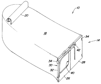
F igure 2 is an elevated perspective view of the bag and door assembly.
F igure 3 is an elevated perspective view of door assembly.
F-igure 4 is a front view of the framework and discharge chute hook.
F igure 5 is a c,ut-away view taken along line 6 of Figure 5 illustrating the door assembly and
framework when mounted to the discharge chute.
F igure 6 is a view similar to that taken of Figure 6, showing however, the door being slidably
removcd from the discharge chute hook.

DESCRIPTION OF THE PREFERRED EMBODIMENT
Looking first to Fig. 1, there is shown a material collection bag or bagger 10 carried
at the rear of ;3 walk-behind lawn mower 12, the mower 12 being illustrated in phantom. The
bagger 10 includes a door assembly 14 which secures it to the discharge chute 16 of the
rnower 10.
Looking also to the enlarged views found in Figs. 2 and 3, it can be seen that the
bagger 10 includes a clippings container 18, which in the preferred embodiment is made of
a soft materiall such as cloth. At the rearward portion of the bagger 10, there is secured a
handle 20 for supporting the rear of the bag 10 on the mower push handle 22. At its forward
portion, the bagger 10 includes an opening 24 wherein a door assembly 14 is mounted. As
35 best seen in Fig. 3, the door assembly 14 includes two separate doors 26 and 28 which are

CA 022288~6 1998-03-09


carried on a rod like framework 30 which in is turn secured to the cloth container 18 at its
opening. The framework 30 takes the form of a rectangle and includes laterally spaced-apart
and generally vertically extending side members or legs 32. To each of the legs 32 is
attached one of the doors 26 and 28, see Figs. 3 and 4. These doors 26 and 28 are, in the
5 preferable embodiment, made of a composite material such as plastic and include portions
34 which can be slidably positioned on the vertical legs 32 and snapped into place to hold
them to the re!spective legs 32. Reinforcing ribs 36 have been provided in the preferred
embodiment.
As is also shown in Fig. 4, the doors 26 and 28 are mounted for swingable
10 rnovement about vertical axis 38 extending through the laterally spaced-apart vertical legs
'32 to permit them to open as shown in Fig. 3 or be moved to their closed position as
illlustrated in Fig. 2. The left door 26 includes an opening 40 through which material can be
received from the discharge chute 16.
The fnamework 30 includes a front handle 42 which is integrally formed into it. The
front and rear handles 42 and 20 support the bagger 10 on the lawn mower 12 and provide
ready handgrips for the operator to remove the bagger 10 from the lawn mower 12 and
c:arry it to a se!parate location for disposal of the clippings.
Looking now to Figs. 4, 5, and 6, the framework 30 with its handle 42 and the chute
rod 44 and support hook 46 are illustrated. The handle 42 includes two slotted areas 48
formed to fit around and slide along the hooked portion 46 of the rod 44 secured to the
c:hute 16. As can be seen in Figs. 5 and 6, the hook 46 projects upwardly and rearwardly.
In operation, the bagger 10 would be mounted to the mower 12 as illustrated in Fig.
1. The rear handle 20 would be carried on the push handle 22 while the front handle 42
would carried on the hook 46 to support the bagger 10 at the rear of the discharge chute 16,
iallowing material propelled through the chute 16 to pass through the opening 40 in the left
cloor 26 and into the bag 18. When the bag 18 has been sufficiently filled and the operator
wants to empty the bag 18, he would grasp the first and second handles 20 and 42, see Fig.
2, to remove bag 18 from the mower 12. He would first raise the rear handle 20 so that the
front handle 42 could be slidably moved from the position illustrated in Fig. 5 to the position
illustrated in Fig. 6. Since the bars 50 and 52 which form the sides of the slots are canted
r,elative to the hook 46, the front handle 42 can be slidably moved upwardly along the hook
46 to remove the front handle 42 from the hook 46 and the bagger 10 from the mower 12.
\/Vith the doori 26 and 28 in their closed position, as illustrated in Fig. 2, the bagger
assembly 10 c:ould be transported to a location where the material could be emptied from
the bag 18.


CA 022288~6 1998-03-09


To empty the bag 18, the operator would keep the doors 26 and 28 in their closedposition and insert that end of the bagger 10 into the refuse can or bag. As the rear of the
bagger 10 is raised, the doors 26 and 28 could open, permitting the material to fall through
the opening 24 and into the refuse bag. Since the doors 26 and 28 are small, approximately
5 one half the size of the opening 24, and pivot about their laterally spaced-apart sides at the
legs 32, they allow the end of the bagger 10 to be inserted into most refuse cans and bags
uuhile they are closed or open. Further, they will not substantially impede the discharge of
c:lippings through the opening 24 of the bag 18.

Dessin représentatif
Une figure unique qui représente un dessin illustrant l'invention.
États administratifs

Pour une meilleure compréhension de l'état de la demande ou brevet qui figure sur cette page, la rubrique Mise en garde , et les descriptions de Brevet , États administratifs , Taxes périodiques et Historique des paiements devraient être consultées.

États administratifs

Titre Date
Date de délivrance prévu 2001-10-16
(22) Dépôt 1998-03-09
Requête d'examen 1998-03-09
(41) Mise à la disponibilité du public 1998-12-09
(45) Délivré 2001-10-16
Réputé périmé 2007-03-09

Historique d'abandonnement

Il n'y a pas d'historique d'abandonnement

Historique des paiements

Type de taxes Anniversaire Échéance Montant payé Date payée
Requête d'examen 400,00 $ 1998-03-09
Enregistrement de documents 100,00 $ 1998-03-09
Le dépôt d'une demande de brevet 300,00 $ 1998-03-09
Taxe de maintien en état - Demande - nouvelle loi 2 2000-03-09 100,00 $ 2000-03-09
Taxe de maintien en état - Demande - nouvelle loi 3 2001-03-09 100,00 $ 2001-03-08
Taxe finale 300,00 $ 2001-07-12
Taxe de maintien en état - brevet - nouvelle loi 4 2002-03-11 100,00 $ 2002-03-08
Taxe de maintien en état - brevet - nouvelle loi 5 2003-03-10 150,00 $ 2003-03-07
Taxe de maintien en état - brevet - nouvelle loi 6 2004-03-09 200,00 $ 2004-02-20
Taxe de maintien en état - brevet - nouvelle loi 7 2005-03-09 200,00 $ 2005-02-21
Titulaires au dossier

Les titulaires actuels et antérieures au dossier sont affichés en ordre alphabétique.

Titulaires actuels au dossier
DEERE & COMPANY
Titulaires antérieures au dossier
HOPKINS, JOHN WILLIAM
LEASURE, JEREMY DOUGLAS
Les propriétaires antérieurs qui ne figurent pas dans la liste des « Propriétaires au dossier » apparaîtront dans d'autres documents au dossier.
Documents

Pour visionner les fichiers sélectionnés, entrer le code reCAPTCHA :


Pour visualiser une image, cliquer sur un lien dans la colonne description du document. Pour télécharger l'image (les images), cliquer l'une ou plusieurs cases à cocher dans la première colonne et ensuite cliquer sur le bouton "Télécharger sélection en format PDF (archive Zip)" ou le bouton "Télécharger sélection (en un fichier PDF fusionné)".

Liste des documents de brevet publiés et non publiés sur la BDBC .

Si vous avez des difficultés à accéder au contenu, veuillez communiquer avec le Centre de services à la clientèle au 1-866-997-1936, ou envoyer un courriel au Centre de service à la clientèle de l'OPIC.


Description du
Document 
Date
(yyyy-mm-dd) 
Nombre de pages   Taille de l'image (Ko) 
Abrégé 1998-03-09 1 17
Page couverture 1998-12-17 1 49
Description 1998-03-09 4 172
Revendications 1998-03-09 1 46
Dessins 1998-03-09 6 79
Dessins représentatifs 2001-10-01 1 7
Page couverture 2001-10-01 1 36
Dessins représentatifs 1998-12-17 1 7
Correspondance 2001-07-12 1 24
Cession 1998-03-09 5 174