Language selection

Search

Patent 2245385 Summary

Third-party information liability

Some of the information on this Web page has been provided by external sources. The Government of Canada is not responsible for the accuracy, reliability or currency of the information supplied by external sources. Users wishing to rely upon this information should consult directly with the source of the information. Content provided by external sources is not subject to official languages, privacy and accessibility requirements.

Claims and Abstract availability

Any discrepancies in the text and image of the Claims and Abstract are due to differing posting times. Text of the Claims and Abstract are posted:

  • At the time the application is open to public inspection;
  • At the time of issue of the patent (grant).
(12) Patent: (11) CA 2245385
(54) English Title: MACHINE FOR POLISHING RAILWAY VEHICLE WHEEL AXLES
(54) French Title: MACHINE UTILISEE POUR POLIR LES ESSIEUX DE VEHICULES DE CHEMIN DE FER
Status: Deemed expired
Bibliographic Data
(51) International Patent Classification (IPC):
  • B24B 21/16 (2006.01)
  • B24B 5/30 (2006.01)
  • B24B 5/36 (2006.01)
  • B24B 21/02 (2006.01)
(72) Inventors :
  • SPINASSE, JOSE CARLOS (Brazil)
(73) Owners :
  • COMPANHIA VALE DO RIO DOCE (Brazil)
(71) Applicants :
  • COMPANHIA VALE DO RIO DOCE (Brazil)
(74) Agent: MOFFAT & CO.
(74) Associate agent:
(45) Issued: 2006-09-12
(22) Filed Date: 1998-09-21
(41) Open to Public Inspection: 1999-03-22
Examination requested: 2002-01-15
Availability of licence: N/A
(25) Language of filing: English

Patent Cooperation Treaty (PCT): No

(30) Application Priority Data:
Application No. Country/Territory Date
PI 9704090-8 Brazil 1997-09-22

Abstracts

English Abstract

A machine for polishing railway vehicle wheel axles comprising a U-shaped basic structure with a cradle form, on the vertical double walls of which are arranged a pair of support rollers for the respective wheels of a railway axle. A driving assembly having a pair of support arms for abrasive belts is disposed on the intermediate horizontal wall of said cradle and said arms being selective and intermittently displaced from one side to the other between the gap defined by the vertical double walls and selective and vertically displaced upwards between the intermediate horizontal wall of the cradle. The axle to be milled is kept on a horizontal plan in view of the action of the wheels.


French Abstract

Une machine utilisée pour polir les essieux de véhicules de chemin de fer composée d'une structure de base en U avec châssis, sur les murs verticaux duquel sont placés une paire de galets d'appui pour les roues respectives d'un essieu de chemin de fer. Le mur horizontal intermédiaire dudit châssis présente un ensemble d'entraînement avec une paire de bras de soutien pour les courroies abrasives et lesdits bras sont déplacés de manière sélective et intermittente d'un côté à l'entre entre l'écart défini par les murs doubles verticaux et déplacés de manière sélective et verticale vers le haut entre le mur horizontal du châssis. L'essieu à polir est conservé sur le plan horizontal à la vue du fonctionnement des roues.

Claims

Note: Claims are shown in the official language in which they were submitted.


7

WHAT IS CLAIMED IS:

1. A machine for polishing a railway vehicle wheel axle, said machine
comprising:
U-shaped basic structure with a cradle form, having a plurality of vertical
double
walls attached to a respective one of a pair of support rollers, said support
rollers support a plurality of respective wheels of a railway axle; and
a driving assembly having a pair of support arms for abrasive belts is
attached to
an intermediate horizontal wall of the cradle, said pair of support arms is
selectively and intermittently displaced from one side to a second side
between
a gap defined by the plurality of vertical double walls and selectively and
vertically displaced upwards between the intermediate horizontal wall of the
cradle and the respective wheels of the railway axle.

2. A machine according to claim 1, wherein the axle to be milled is kept on a
horizontal plan by action of a plurality of wheels bearing together with the
support rolls.

3. A machine according to claim 1, wherein inverted L-profiles are disposed
into an inner face of said vertical double walls, and on which plurality of
corresponding transverse axle ends are attached.

4. A machine according to claim 1, further comprising a plurality of electric
motors, a valve assembly, and a plurality of hydraulic arms, wherein said
plurality of hydraulic arms, said plurality of electric motors, said driving
assembly
and said valve assembly are attached by bearings to a plurality of
corresponding
transverse axle ends attached to said plurality of vertical double walls by
inverted L-profiles.

5. A machine according to claim 1, wherein the mentioned driving assembly
interconnects an electric motor axle with an upper transverse driving rod
which


8

is kept between a pair of transverse axles assembled for supporting the two
endless abrasive belts.

6. A machine according to claim 1, wherein the endless abrasive belts are
lateral and oscillatory displaced by hydraulic arms, and are provided with
vertical
regulation upwards or downwards by bolts and regulating handles provided
between a plurality of transverse axles and a suspending plate incorporated
underneath said plurality of axles and a driving rod.

Description

Note: Descriptions are shown in the official language in which they were submitted.


CA 02245385 1998-09-21
1.
"MACHINE FOR POLISHING RAILWAY VEHICLE WHEEL AXLES"
DESCRIPTION OF THE INVENTION
The present invention refers to a machine for polishing
railway vehicle wheel axles, and more specifically to an
automated machine to be driven by a driving unit and
hydraulically moved for promoting the polishing of almost
all the extension of the wheel axle neck.
As is well known by those skilled in the art, the milling
of locomotive wheel axles which are rough along the bearing
neck and out of the pattern preset by the manufacturer is
presently carried out on a horizontal lathe.
In spite of being broadly used, this method shows a number
of drawbacks among which may be cited the long time and
complexity for displacing and positioning the axle to be
worked up at the machining center and the likelihood of
individually performing that task.
The machining on a horizontal lathe requires the operator
to displace the wheel from the locomotive car disassembling
shop to the machining center or sector, such displacement
being carried out with the help of stackers or equivalent

CA 02245385 1998-09-21
2
conveyors.
Another inconvenience in this conventional milling
treatment of wheel axles refers to the fact that besides
the need of stackers for conveying the axle to be milled,
it is required to provide an overhead crane for positioning
the wheel axle by the horizontal lathe, what requires time
and ability of the operator to perform this procedure.
Another inconvenience when carrying out this milling is the
fact that it is required to assemble a special equipment by
the horizontal lathe for milling the crankshaft.
A further inconvenience in this conventional technique is
the fact that it is possible to mill the one by one the
axle necks, what slows the process in view of the number of
axles present in a locomotive.
OBJECTIVES OF THE INVENTION
Therefore, one object of this invention is to provide a
machine for polishing railway vehicle wheel axles which
allows for a fast and simple displacement and positioning
operation of the axle to be machined at the machining
center.

CA 02245385 2004-10-27
3
Another object of this invention is to provide a machine
for polishing railway vehicle wheel axles which does not
require the operator to displace the wheel from the
locomotive car disassembling shop to the machining center
or sector, thus eliminating the need to provide starkers or
equivalent conveyors.
Another object of this invention is to provide a machine
for polishing railway vehicle wheel axles which does not
require the provision of an overhead crane for positioning
the wheel axle by the horizontal lathe, thus minimizing the
time for performing the procedure.
Another object of this invention is to provide a machine
for polishing railway vehicle wheel axles which does not
require the assembling- of a special equipment by the
horizontal lathe for milling the crankshaft.
Summary of the invention
According to the present invention, there is provided a machine for polishing
a
railway vehicle wheel axle, said machine comprising:
U-shaped basic structure with a cradle form, having a plurality of vertical
double
walls attached to a respective one of a pair of support rollers, said support
rollers support a plurality of respective wheels of a railway axle; and
a driving assembly having a pair of support arms for abrasive belts is
attached to
an intermediate horizontal wall of the cradle, said pair of support arms is

CA 02245385 2004-10-27
4
selectively and intermittently displaced from one side to a second side
between
a gap defined by the plurality of vertical double walls and selectively and
vertically displaced upwards between the intermediate horizontal wall of the
cradle and the respective wheels of the railway axle.
Preferably, the axle to be milled is kept on a horizontal plan in view of the
action
of the wheel bearing together with the support rolls.
BRIEF DESCRIPTION OF THE DRAWINGS
The present invention shall now be described with reference
to the drawings which represent a preferred embodiment of
the invention and wherein:
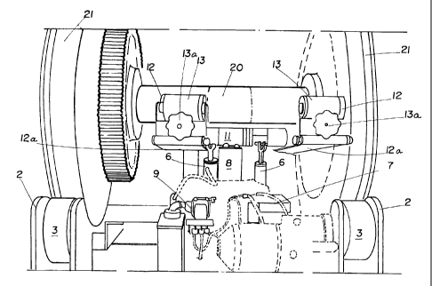
- Figure 1 is a perspective view of the machine
according to the invention supporting a wheel which axle is
to be milled, the abrasive belt being inoperative; and
- Figure 2 shows an expanded detailed perspective view
of the machine as shown in Figure 1 wherein the wheel axle

CA 02245385 1998-09-21
is being polished by the abrasive belts.
DETAILED DESCRIPTION OF THE INVENTION
5
According to the Figures, the machine for polishing railway
vehicle wheel axles object of this invention comprises a U-
shaped basic structure 10 with a cradle form, having a
lower and intermediate horizontal wall 1 and double
vertical end walls 2. Between these end walls a pair of
support rollers 3 is arranged on which are supported the
respective wheels 21 of a railway axle 20.
Into the inner face of said vertical double walls 2,
inverted L-profiles 4 are disposed on which the
corresponding transverse axle ends 5 are attached. On the
transverse axle ends 5 the hydraulic arms 6, electric
motors 7, driving assembly 8 and valve assembly 9 are
arranged by attachment thereto into suitable bearings.
The driving assembly 8 interconnects the electric motor
axle 7 with an upper transverse driving rod 11 which is
kept between a pair of transverse axles 12 assembled for
supporting two endless abrasive belts 13.

CA 02245385 1998-09-21
6
The endless abrasive belts 13 are rotatory actuated by the
driving assembly 8. The endless abrasive belts 13 are
lateral and oscillatory displaced by hydraulic arms 6, and
are provided with vertical regulation upwards or downwards
by bolts and regulating handles 13a provided between the
transverse axles 12 and a suspending plate 12a incorporated
underneath axle 12 and driving rod 11.

Representative Drawing
A single figure which represents the drawing illustrating the invention.
Administrative Status

For a clearer understanding of the status of the application/patent presented on this page, the site Disclaimer , as well as the definitions for Patent , Administrative Status , Maintenance Fee  and Payment History  should be consulted.

Administrative Status

Title Date
Forecasted Issue Date 2006-09-12
(22) Filed 1998-09-21
(41) Open to Public Inspection 1999-03-22
Examination Requested 2002-01-15
(45) Issued 2006-09-12
Deemed Expired 2016-09-21

Abandonment History

There is no abandonment history.

Payment History

Fee Type Anniversary Year Due Date Amount Paid Paid Date
Application Fee $300.00 1998-09-21
Registration of a document - section 124 $100.00 1999-12-20
Maintenance Fee - Application - New Act 2 2000-09-21 $100.00 2000-08-21
Maintenance Fee - Application - New Act 3 2001-09-21 $100.00 2001-09-04
Request for Examination $400.00 2002-01-15
Maintenance Fee - Application - New Act 4 2002-09-23 $100.00 2002-08-15
Maintenance Fee - Application - New Act 5 2003-09-22 $150.00 2003-09-03
Maintenance Fee - Application - New Act 6 2004-09-21 $200.00 2004-09-01
Maintenance Fee - Application - New Act 7 2005-09-21 $200.00 2005-09-14
Final Fee $300.00 2006-06-28
Maintenance Fee - Patent - New Act 8 2006-09-21 $200.00 2006-09-13
Maintenance Fee - Patent - New Act 9 2007-09-21 $200.00 2007-07-05
Maintenance Fee - Patent - New Act 10 2008-09-22 $250.00 2008-06-04
Maintenance Fee - Patent - New Act 11 2009-09-21 $250.00 2009-09-09
Maintenance Fee - Patent - New Act 12 2010-09-21 $250.00 2010-09-14
Maintenance Fee - Patent - New Act 13 2011-09-21 $250.00 2011-09-08
Maintenance Fee - Patent - New Act 14 2012-09-21 $250.00 2012-07-30
Maintenance Fee - Patent - New Act 15 2013-09-23 $450.00 2013-08-26
Maintenance Fee - Patent - New Act 16 2014-09-22 $650.00 2014-10-21
Owners on Record

Note: Records showing the ownership history in alphabetical order.

Current Owners on Record
COMPANHIA VALE DO RIO DOCE
Past Owners on Record
SPINASSE, JOSE CARLOS
Past Owners that do not appear in the "Owners on Record" listing will appear in other documentation within the application.
Documents

To view selected files, please enter reCAPTCHA code :


To view images, click a link in the Document Description column. To download the documents, select one or more checkboxes in the first column and then click the "Download Selected in PDF format (Zip Archive)" or the "Download Selected as Single PDF" button.

List of published and non-published patent-specific documents on the CPD .

If you have any difficulty accessing content, you can call the Client Service Centre at 1-866-997-1936 or send them an e-mail at CIPO Client Service Centre.


Document
Description 
Date
(yyyy-mm-dd) 
Number of pages   Size of Image (KB) 
Representative Drawing 1999-04-12 1 11
Description 1998-09-21 6 146
Abstract 1998-09-21 1 21
Claims 1998-09-21 2 48
Drawings 1998-09-21 2 43
Cover Page 1999-04-12 1 53
Description 2004-10-27 6 152
Claims 2004-10-27 2 56
Claims 2005-07-05 2 55
Representative Drawing 2006-08-10 1 17
Cover Page 2006-08-10 1 47
Fees 2001-09-04 1 32
Correspondence 1998-10-13 1 29
Assignment 1998-09-21 3 74
Assignment 1999-12-20 2 90
Correspondence 2000-01-17 1 2
Assignment 2000-03-03 2 61
Prosecution-Amendment 2002-01-15 1 30
Fees 2003-09-03 1 30
Fees 2000-08-21 1 30
Fees 2002-08-15 1 30
Fees 2004-09-01 1 28
Prosecution-Amendment 2004-08-04 3 59
Prosecution-Amendment 2004-10-27 6 163
Prosecution-Amendment 2005-06-20 2 35
Prosecution-Amendment 2005-07-05 3 50
Fees 2005-09-14 1 27
Correspondence 2006-06-28 1 31
Fees 2006-09-13 1 34
Fees 2007-07-05 1 47
Fees 2008-06-04 1 39
Correspondence 2010-08-10 1 45
Correspondence 2012-07-04 2 69
Correspondence 2012-07-12 1 12
Correspondence 2012-07-12 1 15
Fees 2012-07-30 1 48
Fees 2013-08-26 1 47
Fees 2014-10-21 1 53