Sélection de la langue

Search

Sommaire du brevet 2245385 

Énoncé de désistement de responsabilité concernant l'information provenant de tiers

Une partie des informations de ce site Web a été fournie par des sources externes. Le gouvernement du Canada n'assume aucune responsabilité concernant la précision, l'actualité ou la fiabilité des informations fournies par les sources externes. Les utilisateurs qui désirent employer cette information devraient consulter directement la source des informations. Le contenu fourni par les sources externes n'est pas assujetti aux exigences sur les langues officielles, la protection des renseignements personnels et l'accessibilité.

Disponibilité de l'Abrégé et des Revendications

L'apparition de différences dans le texte et l'image des Revendications et de l'Abrégé dépend du moment auquel le document est publié. Les textes des Revendications et de l'Abrégé sont affichés :

  • lorsque la demande peut être examinée par le public;
  • lorsque le brevet est émis (délivrance).
(12) Brevet: (11) CA 2245385
(54) Titre français: MACHINE UTILISEE POUR POLIR LES ESSIEUX DE VEHICULES DE CHEMIN DE FER
(54) Titre anglais: MACHINE FOR POLISHING RAILWAY VEHICLE WHEEL AXLES
Statut: Réputé périmé
Données bibliographiques
(51) Classification internationale des brevets (CIB):
  • B24B 21/16 (2006.01)
  • B24B 5/30 (2006.01)
  • B24B 5/36 (2006.01)
  • B24B 21/02 (2006.01)
(72) Inventeurs :
  • SPINASSE, JOSE CARLOS (Brésil)
(73) Titulaires :
  • COMPANHIA VALE DO RIO DOCE (Brésil)
(71) Demandeurs :
  • COMPANHIA VALE DO RIO DOCE (Brésil)
(74) Agent: MOFFAT & CO.
(74) Co-agent:
(45) Délivré: 2006-09-12
(22) Date de dépôt: 1998-09-21
(41) Mise à la disponibilité du public: 1999-03-22
Requête d'examen: 2002-01-15
Licence disponible: S.O.
(25) Langue des documents déposés: Anglais

Traité de coopération en matière de brevets (PCT): Non

(30) Données de priorité de la demande:
Numéro de la demande Pays / territoire Date
PI 9704090-8 Brésil 1997-09-22

Abrégés

Abrégé français

Une machine utilisée pour polir les essieux de véhicules de chemin de fer composée d'une structure de base en U avec châssis, sur les murs verticaux duquel sont placés une paire de galets d'appui pour les roues respectives d'un essieu de chemin de fer. Le mur horizontal intermédiaire dudit châssis présente un ensemble d'entraînement avec une paire de bras de soutien pour les courroies abrasives et lesdits bras sont déplacés de manière sélective et intermittente d'un côté à l'entre entre l'écart défini par les murs doubles verticaux et déplacés de manière sélective et verticale vers le haut entre le mur horizontal du châssis. L'essieu à polir est conservé sur le plan horizontal à la vue du fonctionnement des roues.


Abrégé anglais

A machine for polishing railway vehicle wheel axles comprising a U-shaped basic structure with a cradle form, on the vertical double walls of which are arranged a pair of support rollers for the respective wheels of a railway axle. A driving assembly having a pair of support arms for abrasive belts is disposed on the intermediate horizontal wall of said cradle and said arms being selective and intermittently displaced from one side to the other between the gap defined by the vertical double walls and selective and vertically displaced upwards between the intermediate horizontal wall of the cradle. The axle to be milled is kept on a horizontal plan in view of the action of the wheels.

Revendications

Note : Les revendications sont présentées dans la langue officielle dans laquelle elles ont été soumises.


7

WHAT IS CLAIMED IS:

1. A machine for polishing a railway vehicle wheel axle, said machine
comprising:
U-shaped basic structure with a cradle form, having a plurality of vertical
double
walls attached to a respective one of a pair of support rollers, said support
rollers support a plurality of respective wheels of a railway axle; and
a driving assembly having a pair of support arms for abrasive belts is
attached to
an intermediate horizontal wall of the cradle, said pair of support arms is
selectively and intermittently displaced from one side to a second side
between
a gap defined by the plurality of vertical double walls and selectively and
vertically displaced upwards between the intermediate horizontal wall of the
cradle and the respective wheels of the railway axle.

2. A machine according to claim 1, wherein the axle to be milled is kept on a
horizontal plan by action of a plurality of wheels bearing together with the
support rolls.

3. A machine according to claim 1, wherein inverted L-profiles are disposed
into an inner face of said vertical double walls, and on which plurality of
corresponding transverse axle ends are attached.

4. A machine according to claim 1, further comprising a plurality of electric
motors, a valve assembly, and a plurality of hydraulic arms, wherein said
plurality of hydraulic arms, said plurality of electric motors, said driving
assembly
and said valve assembly are attached by bearings to a plurality of
corresponding
transverse axle ends attached to said plurality of vertical double walls by
inverted L-profiles.

5. A machine according to claim 1, wherein the mentioned driving assembly
interconnects an electric motor axle with an upper transverse driving rod
which


8

is kept between a pair of transverse axles assembled for supporting the two
endless abrasive belts.

6. A machine according to claim 1, wherein the endless abrasive belts are
lateral and oscillatory displaced by hydraulic arms, and are provided with
vertical
regulation upwards or downwards by bolts and regulating handles provided
between a plurality of transverse axles and a suspending plate incorporated
underneath said plurality of axles and a driving rod.

Description

Note : Les descriptions sont présentées dans la langue officielle dans laquelle elles ont été soumises.

CA 02245385 1998-09-21
1.
"MACHINE FOR POLISHING RAILWAY VEHICLE WHEEL AXLES"
DESCRIPTION OF THE INVENTION
The present invention refers to a machine for polishing
railway vehicle wheel axles, and more specifically to an
automated machine to be driven by a driving unit and
hydraulically moved for promoting the polishing of almost
all the extension of the wheel axle neck.
As is well known by those skilled in the art, the milling
of locomotive wheel axles which are rough along the bearing
neck and out of the pattern preset by the manufacturer is
presently carried out on a horizontal lathe.
In spite of being broadly used, this method shows a number
of drawbacks among which may be cited the long time and
complexity for displacing and positioning the axle to be
worked up at the machining center and the likelihood of
individually performing that task.
The machining on a horizontal lathe requires the operator
to displace the wheel from the locomotive car disassembling
shop to the machining center or sector, such displacement
being carried out with the help of stackers or equivalent

CA 02245385 1998-09-21
2
conveyors.
Another inconvenience in this conventional milling
treatment of wheel axles refers to the fact that besides
the need of stackers for conveying the axle to be milled,
it is required to provide an overhead crane for positioning
the wheel axle by the horizontal lathe, what requires time
and ability of the operator to perform this procedure.
Another inconvenience when carrying out this milling is the
fact that it is required to assemble a special equipment by
the horizontal lathe for milling the crankshaft.
A further inconvenience in this conventional technique is
the fact that it is possible to mill the one by one the
axle necks, what slows the process in view of the number of
axles present in a locomotive.
OBJECTIVES OF THE INVENTION
Therefore, one object of this invention is to provide a
machine for polishing railway vehicle wheel axles which
allows for a fast and simple displacement and positioning
operation of the axle to be machined at the machining
center.

CA 02245385 2004-10-27
3
Another object of this invention is to provide a machine
for polishing railway vehicle wheel axles which does not
require the operator to displace the wheel from the
locomotive car disassembling shop to the machining center
or sector, thus eliminating the need to provide starkers or
equivalent conveyors.
Another object of this invention is to provide a machine
for polishing railway vehicle wheel axles which does not
require the provision of an overhead crane for positioning
the wheel axle by the horizontal lathe, thus minimizing the
time for performing the procedure.
Another object of this invention is to provide a machine
for polishing railway vehicle wheel axles which does not
require the assembling- of a special equipment by the
horizontal lathe for milling the crankshaft.
Summary of the invention
According to the present invention, there is provided a machine for polishing
a
railway vehicle wheel axle, said machine comprising:
U-shaped basic structure with a cradle form, having a plurality of vertical
double
walls attached to a respective one of a pair of support rollers, said support
rollers support a plurality of respective wheels of a railway axle; and
a driving assembly having a pair of support arms for abrasive belts is
attached to
an intermediate horizontal wall of the cradle, said pair of support arms is

CA 02245385 2004-10-27
4
selectively and intermittently displaced from one side to a second side
between
a gap defined by the plurality of vertical double walls and selectively and
vertically displaced upwards between the intermediate horizontal wall of the
cradle and the respective wheels of the railway axle.
Preferably, the axle to be milled is kept on a horizontal plan in view of the
action
of the wheel bearing together with the support rolls.
BRIEF DESCRIPTION OF THE DRAWINGS
The present invention shall now be described with reference
to the drawings which represent a preferred embodiment of
the invention and wherein:
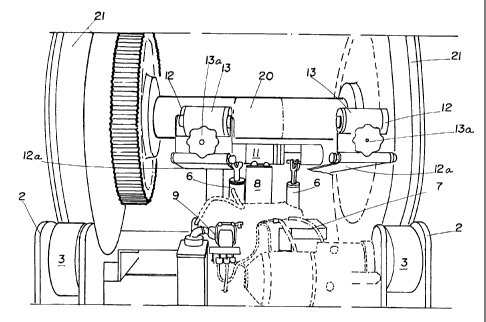
- Figure 1 is a perspective view of the machine
according to the invention supporting a wheel which axle is
to be milled, the abrasive belt being inoperative; and
- Figure 2 shows an expanded detailed perspective view
of the machine as shown in Figure 1 wherein the wheel axle

CA 02245385 1998-09-21
is being polished by the abrasive belts.
DETAILED DESCRIPTION OF THE INVENTION
5
According to the Figures, the machine for polishing railway
vehicle wheel axles object of this invention comprises a U-
shaped basic structure 10 with a cradle form, having a
lower and intermediate horizontal wall 1 and double
vertical end walls 2. Between these end walls a pair of
support rollers 3 is arranged on which are supported the
respective wheels 21 of a railway axle 20.
Into the inner face of said vertical double walls 2,
inverted L-profiles 4 are disposed on which the
corresponding transverse axle ends 5 are attached. On the
transverse axle ends 5 the hydraulic arms 6, electric
motors 7, driving assembly 8 and valve assembly 9 are
arranged by attachment thereto into suitable bearings.
The driving assembly 8 interconnects the electric motor
axle 7 with an upper transverse driving rod 11 which is
kept between a pair of transverse axles 12 assembled for
supporting two endless abrasive belts 13.

CA 02245385 1998-09-21
6
The endless abrasive belts 13 are rotatory actuated by the
driving assembly 8. The endless abrasive belts 13 are
lateral and oscillatory displaced by hydraulic arms 6, and
are provided with vertical regulation upwards or downwards
by bolts and regulating handles 13a provided between the
transverse axles 12 and a suspending plate 12a incorporated
underneath axle 12 and driving rod 11.

Dessin représentatif
Une figure unique qui représente un dessin illustrant l'invention.
États administratifs

Pour une meilleure compréhension de l'état de la demande ou brevet qui figure sur cette page, la rubrique Mise en garde , et les descriptions de Brevet , États administratifs , Taxes périodiques et Historique des paiements devraient être consultées.

États administratifs

Titre Date
Date de délivrance prévu 2006-09-12
(22) Dépôt 1998-09-21
(41) Mise à la disponibilité du public 1999-03-22
Requête d'examen 2002-01-15
(45) Délivré 2006-09-12
Réputé périmé 2016-09-21

Historique d'abandonnement

Il n'y a pas d'historique d'abandonnement

Historique des paiements

Type de taxes Anniversaire Échéance Montant payé Date payée
Le dépôt d'une demande de brevet 300,00 $ 1998-09-21
Enregistrement de documents 100,00 $ 1999-12-20
Taxe de maintien en état - Demande - nouvelle loi 2 2000-09-21 100,00 $ 2000-08-21
Taxe de maintien en état - Demande - nouvelle loi 3 2001-09-21 100,00 $ 2001-09-04
Requête d'examen 400,00 $ 2002-01-15
Taxe de maintien en état - Demande - nouvelle loi 4 2002-09-23 100,00 $ 2002-08-15
Taxe de maintien en état - Demande - nouvelle loi 5 2003-09-22 150,00 $ 2003-09-03
Taxe de maintien en état - Demande - nouvelle loi 6 2004-09-21 200,00 $ 2004-09-01
Taxe de maintien en état - Demande - nouvelle loi 7 2005-09-21 200,00 $ 2005-09-14
Taxe finale 300,00 $ 2006-06-28
Taxe de maintien en état - brevet - nouvelle loi 8 2006-09-21 200,00 $ 2006-09-13
Taxe de maintien en état - brevet - nouvelle loi 9 2007-09-21 200,00 $ 2007-07-05
Taxe de maintien en état - brevet - nouvelle loi 10 2008-09-22 250,00 $ 2008-06-04
Taxe de maintien en état - brevet - nouvelle loi 11 2009-09-21 250,00 $ 2009-09-09
Taxe de maintien en état - brevet - nouvelle loi 12 2010-09-21 250,00 $ 2010-09-14
Taxe de maintien en état - brevet - nouvelle loi 13 2011-09-21 250,00 $ 2011-09-08
Taxe de maintien en état - brevet - nouvelle loi 14 2012-09-21 250,00 $ 2012-07-30
Taxe de maintien en état - brevet - nouvelle loi 15 2013-09-23 450,00 $ 2013-08-26
Taxe de maintien en état - brevet - nouvelle loi 16 2014-09-22 650,00 $ 2014-10-21
Titulaires au dossier

Les titulaires actuels et antérieures au dossier sont affichés en ordre alphabétique.

Titulaires actuels au dossier
COMPANHIA VALE DO RIO DOCE
Titulaires antérieures au dossier
SPINASSE, JOSE CARLOS
Les propriétaires antérieurs qui ne figurent pas dans la liste des « Propriétaires au dossier » apparaîtront dans d'autres documents au dossier.
Documents

Pour visionner les fichiers sélectionnés, entrer le code reCAPTCHA :


Pour visualiser une image, cliquer sur un lien dans la colonne description du document. Pour télécharger l'image (les images), cliquer l'une ou plusieurs cases à cocher dans la première colonne et ensuite cliquer sur le bouton "Télécharger sélection en format PDF (archive Zip)" ou le bouton "Télécharger sélection (en un fichier PDF fusionné)".

Liste des documents de brevet publiés et non publiés sur la BDBC .

Si vous avez des difficultés à accéder au contenu, veuillez communiquer avec le Centre de services à la clientèle au 1-866-997-1936, ou envoyer un courriel au Centre de service à la clientèle de l'OPIC.


Description du
Document 
Date
(yyyy-mm-dd) 
Nombre de pages   Taille de l'image (Ko) 
Dessins représentatifs 1999-04-12 1 11
Description 1998-09-21 6 146
Abrégé 1998-09-21 1 21
Revendications 1998-09-21 2 48
Dessins 1998-09-21 2 43
Page couverture 1999-04-12 1 53
Description 2004-10-27 6 152
Revendications 2004-10-27 2 56
Revendications 2005-07-05 2 55
Dessins représentatifs 2006-08-10 1 17
Page couverture 2006-08-10 1 47
Taxes 2001-09-04 1 32
Correspondance 1998-10-13 1 29
Cession 1998-09-21 3 74
Cession 1999-12-20 2 90
Correspondance 2000-01-17 1 2
Cession 2000-03-03 2 61
Poursuite-Amendment 2002-01-15 1 30
Taxes 2003-09-03 1 30
Taxes 2000-08-21 1 30
Taxes 2002-08-15 1 30
Taxes 2004-09-01 1 28
Poursuite-Amendment 2004-08-04 3 59
Poursuite-Amendment 2004-10-27 6 163
Poursuite-Amendment 2005-06-20 2 35
Poursuite-Amendment 2005-07-05 3 50
Taxes 2005-09-14 1 27
Correspondance 2006-06-28 1 31
Taxes 2006-09-13 1 34
Taxes 2007-07-05 1 47
Taxes 2008-06-04 1 39
Correspondance 2010-08-10 1 45
Correspondance 2012-07-04 2 69
Correspondance 2012-07-12 1 12
Correspondance 2012-07-12 1 15
Taxes 2012-07-30 1 48
Taxes 2013-08-26 1 47
Taxes 2014-10-21 1 53