Language selection

Search

Patent 2255464 Summary

Third-party information liability

Some of the information on this Web page has been provided by external sources. The Government of Canada is not responsible for the accuracy, reliability or currency of the information supplied by external sources. Users wishing to rely upon this information should consult directly with the source of the information. Content provided by external sources is not subject to official languages, privacy and accessibility requirements.

Claims and Abstract availability

Any discrepancies in the text and image of the Claims and Abstract are due to differing posting times. Text of the Claims and Abstract are posted:

  • At the time the application is open to public inspection;
  • At the time of issue of the patent (grant).
(12) Patent: (11) CA 2255464
(54) English Title: NEAR-OPTIMAL LOW-COMPLEXITY DECODING OF SPACE-TIME CODES FOR FIXED WIRELESS APPLICATIONS
(54) French Title: DECODAGE QUASI OPTIMAL DE COMPLEXITE REDUITE DE CODES ESPACE-TEMPS POUR DES APPLICATIONS FIXES SANS FIL
Status: Deemed expired
Bibliographic Data
(51) International Patent Classification (IPC):
  • H04B 7/08 (2006.01)
  • H04W 88/00 (2009.01)
(72) Inventors :
  • LO, TITUS (United States of America)
  • TAROKH, VAHID (United States of America)
(73) Owners :
  • AT&T WIRELESS SERVICES, INC. (United States of America)
(71) Applicants :
  • AT&T WIRELESS SERVICES, INC. (United States of America)
(74) Agent: KIRBY EADES GALE BAKER
(74) Associate agent:
(45) Issued: 2002-08-06
(22) Filed Date: 1998-12-10
(41) Open to Public Inspection: 1999-06-23
Examination requested: 1998-12-10
Availability of licence: N/A
(25) Language of filing: English

Patent Cooperation Treaty (PCT): No

(30) Application Priority Data:
Application No. Country/Territory Date
09/063,765 United States of America 1997-12-23

Abstracts

English Abstract

An improved multi-antenna receiver is realized for detecting signals transmitted by a multi-antenna transmitter by summingsumming signals received at the plurality of receiver antennas after multiplying each by a respective constant. The summed signal is applied to a maximum likelihood detector. The respective constants, .lambda.j, where j is an index designating a particular receiver antenna, are determined by evaluating the largest eigenvalue of the matrix AA(A*)T, where A is a vector containing the values .lambda.j, and A is a matrix containing elements .alpha. ij, which is the transfer function between the i th transmitter antenna to the j th receiver antenna. The .alpha. ij terms are determined in the receiver in conventional ways.


French Abstract

Un récepteur multiantennes amélioré sert à détecter des signaux transmis par un récepteur multiantennes en faisant la somme des signaux reçus par la pluralité d'antennes réceptrices après avoir multiplié chacun par une constante respective. Le signal global est appliqué à un détecteur de probabilité maximale. Les constantes respectives j, où j est un indice désignant une antenne réceptrice particulière, sont déterminées en évaluant la valeur propre la plus grande de la matrice A(*)T, où est un vecteur contenant les valeurs j et A est une matrice contenant les éléments ij, qui est la fonction de transfert entre la i-ème antenne émettrice et la j-ème antenne émettrice. Les termes ij sont déterminés dans le récepteur de manière classique.

Claims

Note: Claims are shown in the official language in which they were submitted.


7

Claims:

1. A receiver comprising:
an n plurality of antennas, where n is greater than one;
circuitry for obtaining n signals transmitted from m antennas of a
transmitter, where m is greater than one; and
processing means for
developing a sum signal that corresponds to the addition of said n
signals that are each pre-multiplied by a respective factor .lambda.j, where j
is an
index integer specifying that factor .lambda.j multiplies the signal received
from
antenna j of said n plurality of antennas,
developing values for transfer functions .alpha.ij where i is an index
that references said transmitting antennas, and j is an index that references
said receiving antennas,
developing said factors .lambda.j from said transfer functions, where said
factors are components of a vector .LAMBDA. where .LAMBDA. is an eigenvector
of A, and
where A is a matrix containing said elements .alpha.ij, and
detecting symbols transmitted by said m transmitter antennas
embedded in said sum signal.

2. The receiver of claim 1 where said detecting compares said sum
signal to a signal corresponding to symbols c i possibly transmitted by
transmitting antenna i of said m transmitting antennas multiplied by
corresponding factors .gamma.i.

3. The receiver of claim 2 where said corresponding factor .gamma.i is
related to said factors .lambda.j, for j=1,2,3, . . . , m, and to .alpha.ij.


8


4. The receiver of claim 2 where said detecting minimizes the metric

Image

where R i is said sum signal at time interval t within a frame having L time
intervals, c~ is the symbol that might have been transmitted over
transmitting antenna i at time interval t.


Description

Note: Descriptions are shown in the official language in which they were submitted.


CA 02255464 2001-07-10
1
Near-Optimal Low-Complexity Decoding of Space-Time
Codes
For Fixed Wireless Applications
Background of the Invention
5 This invention relates to wireless systems and, more particularly,
to systems having more than one antenna at the receiver and at the
transmitted.
Physical constraints as well as narrow bandwidth, co-channel
interference, adjacent channel interference, propagation loss and multi-
10 path fading limit the capacity of cellular systems, These are severe
impairments, which liken the wireless channel to a narrow pipe that
impedes the flow of data. Nevertheless, interest in providing high speed
wireless data services is rapidly increasing. Current cellular standards
such as IS-136 can only provide data rates up to 9.6 kbps, using 30 kHz
15 narrowband channels. In order to provide wideband services, such as
multimedia, video conferencing, simultaneous voice and data, etc., it is
desirable to have data rates in the range of 64-144 kbps.
Transmission schemes for multiple antenna systems may be part
of a solution to the problem of the currently available low data rates. In
20 such schemes the problem was addressed in the context of signal
processing.
One prior art arrangement having a single transmitter antenna and
multiple receiver antennas is shown in FIG. 1. Each of the receiver
antennas receives the transmitted signal via a slightly different channel,
25 where each channel i is characterized by transfer function a;. Using an
approach known as "Maximum Ratio Combining", the prior art approach
to detection contemplates multiplying each received signal that had been

CA 02255464 2001-07-10
2
influenced by a; by the complex conjugate signal, a;*, summed, and then
processed.
In U.S. Patent No. 6,115,427 which issued on September 5, 2000,
a coding perspective was adopted to propose space-time coding using
5 multiple transmit and receive antennas. Space-time coding integrates
channel coding, modulation, and multiple transmit antennas to achieve
higher data rates, while simultaneously providing diversity that combats
fading. It may be demonstrated that adding channel coding provides
significant gains over the transmission schemes set forth above. In U.S.
10 Patent No. 6,115,427, space-time codes were designed for transmission
using 2-4 transmit antennas. These codes perform extremely well in
slowly varying fading environments (such as indoor transmission media).
The codes have user bandwidth efficiencies of up to 4 bits/sec/Hz which
are about 3-4 times the efficiency of current systems. Indeed, it can be
15 shown that the designed codes are optimal in terms of the trade-off
between diversity advantage, transmission rate, decoding complexity and
constellation size.
It can also be shown that as the number of antennas is increased,
the gain increases in a manner that is not unlike a mufti-element antenna
20 that is tuned to, say, a particular direction. Unfortunately, however, when
maximum likelihood detection is employed at the receiver, the decoding
complexity increases when the number of transmit and receive antennas

CA 02255464 2001-07-10
3
is increased. It would be obviously advantageous to allow a slightly sub-
optimal detection approach that substantially reduces the receiver's
computation burden.
5 Summary
Such an approach is achieved with a receiver arrangement where
signals received at a plurality of antennas are each multiplied by a
respective constant and then summed prior to being applied to a
maximum likelihood detector. The respective constants, ~,~ , where j is
10 an index designating a particular receiver antenna, are derived f:om a
processor that determines the largest eigenvector of the matrix A,
where A is a vector containing the values ~,l , and A is a matrix
containing elements a~ , which is the transfer function between the i'h
transmitter antenna to the j'h receiver antenna. The a~ terms are
15 determined in the receiver in conventional ways.
Brief Description of the Drawing
FIG. 1 presents a block diagram of Maximal Ratio Combining
detection; and
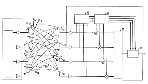
20 FIG. 2 presents a block diagram of an arrangement including a
transmitter having a plurality of antennas, and a receiver having a
plurality of antennas coupled to an efficient detection structure.
Detailed Description
FIG. 2 presents a block diagram of a receiver in accord with the
25 principles of this invention. It includes a transmitter 10 that has an n
plurality of transmitting antenna 1, 2, 3, 4, and a receiver 20 that has an
m plurality of receiver antennas 21, 22, 23, 24. The signals received by
the receiver's antennas are multiplied in elements 25, 26, 27, and 28, and

CA 02255464 2001-07-10
4
summed in adder 30. More specifically, the received signal of antenna j
is multiplied by a value, ~,~ , and summed. The collection of factors ~,~
can be viewed as a vector A . The outputs of the receiver antennas are
also applied to processor 40 which, employing conventional techniques,
5 determines the transfer functions a~ for i=1, 2, 3,..., n and j=1, 2, 3,...,
m. These transfer functions can be evaluated, for example, through the
use of training sequences that are sent by the different transmitter
antennas, one antenna at a time.
The evaluated a;~ signals of processor 40 are applied to
10 processor 45 in FIG. 2 where the multiplier signals ~,~, j=l, 2, 3,..., m
are
computed. Processor 45 also evaluates a set of combined transfer
function values y; , i=1, 2, 3,..., n (which are described in more detail
below). Signals y; of processor 45 and the output signal of adder 30 are
applied to detector 50 which detects the transmitted symbols in
15 accordance with calculations disclosed below.
It is assumed that the symbols transmitted by the antennas of
transmitter 10 have been encoded in blocks of L time frames; and that
fading is constant within a frame. A codeword comprises all of the
symbols transmitted within a frame, and it corresponds, therefore, to
20 C~CZC3.. C4C~CZC3.. C4C~CZC3.. C4.. C~ CZ C3 .. C4
1 I 1 ' 1 2 2 2 ' 2 3 3 3 ' 3 ' m m m ' m~
where the superscript designates the transmitter's antennas and the
subscript designates the time of transmission (or position within a
frame).
From the standpoint of a single transmitting antenna, e.g., antenna
25 1, the signal that is received from antenna 1 in response to a transmitted
symbol crl at time interval t is:

CA 02255464 2001-07-10
5
Rr -Cr(alla'1 -~a12/~'2 -1-al3a'3 +...-~a,ml~,ur)
nr
C, ~ ~.j a,j
j=1
1
= Cr y1
(when noise is ignored). If each ~,j value is set to a *, j , (where a *,~ is
the complex conjugate of a,j ) then the received signal would simply be
nr
2
Rr = c~ ~~ali
.=1
5 yielding a constructive addition.
Of course, the values of ~,j cannot be set to match a *,j and
concurrently to match the values of a * ~ where i ~ 1; and therein lies the
difficulty.
When all n of the transmitting antennas are considered, then the
10 received signal is
n m
R~ _ ~ C~ ~'~la
=1 j=_I
n
= i
Cr yi
i=1
In accordance with the present disclosure, the objective is to
maximize ~ ly; IZ because by doing so, signal R, contains as much
r=1
information about c; , i =1,2,3,...n as is possible. However, it can be
15 easily shown that if a matrix A is constructed such that
n
A=~(~i*)''~r
i=1
where S2; _ (a;, , a; z , a; 3 ...a;", ) , then
r=1

CA 02255464 2001-07-10
6
The receiver, thus, has to maximize AA(A*)'~ , subject to the
constraint IIAlI2 =1. The solution to this problem is to choose A to be
the eigenvector of A which corresponds to the maximum eigenvalue of
A. Accordingly, processor 45 develops the matrix A from the values
5 ofa~ , finds the eigenvalues ofA in a conventional manner, selects the
maximum eigenvalue of A, and creates the vector A . Once A is known,
processor 45 develops signals y; for 1=1, 2, 3,..., n, (where
ni
y; _ ~~,ja~ ), and applies them to detector 50. Finally, detector 50
j=I
minimizes the metric
L n
10 ~ R, - ~ y; c;
from amongst all possible codewords in a conventional manner. As can
be seen, this approach reduces the complexity of decoding by almost a
factor of m.
FIG. 2 depicts separate multipliers to multiply received signals by
15 multiplication factors ~,; , and it depicts separate blocks for elements
30,
40, 45, and 50. It should be understood, however, that different
embodiments are also possible. For example, it is quite conventional to
incorporate all of the above-mentioned elements in a single special
purpose processor, or in a single stored program controlled processor (or
20 a small number of processors). Other modifications and improvements
may also be incorporated, without departing from the spirit and scope of
the invention, which is defined in the following claims.

Representative Drawing
A single figure which represents the drawing illustrating the invention.
Administrative Status

For a clearer understanding of the status of the application/patent presented on this page, the site Disclaimer , as well as the definitions for Patent , Administrative Status , Maintenance Fee  and Payment History  should be consulted.

Administrative Status

Title Date
Forecasted Issue Date 2002-08-06
(22) Filed 1998-12-10
Examination Requested 1998-12-10
(41) Open to Public Inspection 1999-06-23
(45) Issued 2002-08-06
Deemed Expired 2018-12-10

Abandonment History

There is no abandonment history.

Payment History

Fee Type Anniversary Year Due Date Amount Paid Paid Date
Request for Examination $400.00 1998-12-10
Registration of a document - section 124 $100.00 1998-12-10
Application Fee $300.00 1998-12-10
Maintenance Fee - Application - New Act 2 2000-12-11 $100.00 2000-09-27
Maintenance Fee - Application - New Act 3 2001-12-10 $100.00 2001-10-03
Final Fee $300.00 2002-05-16
Maintenance Fee - Patent - New Act 4 2002-12-10 $100.00 2002-12-04
Maintenance Fee - Patent - New Act 5 2003-12-10 $150.00 2003-11-05
Maintenance Fee - Patent - New Act 6 2004-12-10 $200.00 2004-11-04
Maintenance Fee - Patent - New Act 7 2005-12-12 $200.00 2005-11-04
Maintenance Fee - Patent - New Act 8 2006-12-11 $200.00 2006-11-07
Maintenance Fee - Patent - New Act 9 2007-12-10 $200.00 2007-11-07
Maintenance Fee - Patent - New Act 10 2008-12-10 $250.00 2008-11-12
Maintenance Fee - Patent - New Act 11 2009-12-10 $250.00 2009-11-10
Maintenance Fee - Patent - New Act 12 2010-12-10 $250.00 2010-11-17
Maintenance Fee - Patent - New Act 13 2011-12-12 $250.00 2011-11-17
Maintenance Fee - Patent - New Act 14 2012-12-10 $250.00 2012-11-15
Maintenance Fee - Patent - New Act 15 2013-12-10 $450.00 2013-11-14
Maintenance Fee - Patent - New Act 16 2014-12-10 $450.00 2014-11-14
Maintenance Fee - Patent - New Act 17 2015-12-10 $450.00 2015-11-13
Maintenance Fee - Patent - New Act 18 2016-12-12 $450.00 2016-11-10
Owners on Record

Note: Records showing the ownership history in alphabetical order.

Current Owners on Record
AT&T WIRELESS SERVICES, INC.
Past Owners on Record
LO, TITUS
TAROKH, VAHID
Past Owners that do not appear in the "Owners on Record" listing will appear in other documentation within the application.
Documents

To view selected files, please enter reCAPTCHA code :


To view images, click a link in the Document Description column. To download the documents, select one or more checkboxes in the first column and then click the "Download Selected in PDF format (Zip Archive)" or the "Download Selected as Single PDF" button.

List of published and non-published patent-specific documents on the CPD .

If you have any difficulty accessing content, you can call the Client Service Centre at 1-866-997-1936 or send them an e-mail at CIPO Client Service Centre.


Document
Description 
Date
(yyyy-mm-dd) 
Number of pages   Size of Image (KB) 
Cover Page 2002-07-02 1 44
Abstract 1998-12-10 1 20
Description 1998-12-10 6 211
Claims 1998-12-10 2 43
Drawings 1998-12-10 2 35
Description 2001-07-10 6 221
Claims 2001-07-10 2 43
Cover Page 1999-07-08 1 41
Representative Drawing 1999-07-08 1 11
Representative Drawing 2002-07-02 1 12
Prosecution-Amendment 1999-02-26 3 71
Correspondence 2009-09-14 1 15
Correspondence 2009-09-14 1 16
Correspondence 2002-10-31 7 283
Prosecution-Amendment 2001-07-10 10 323
Prosecution-Amendment 2001-04-02 2 66
Correspondence 2002-05-16 1 35
Correspondence 2002-10-15 1 24
Assignment 1998-12-10 6 185
Correspondence 2002-09-25 3 125
Correspondence 2002-10-15 1 13
Correspondence 2009-08-24 2 71