Sélection de la langue

Search

Sommaire du brevet 2255464 

Énoncé de désistement de responsabilité concernant l'information provenant de tiers

Une partie des informations de ce site Web a été fournie par des sources externes. Le gouvernement du Canada n'assume aucune responsabilité concernant la précision, l'actualité ou la fiabilité des informations fournies par les sources externes. Les utilisateurs qui désirent employer cette information devraient consulter directement la source des informations. Le contenu fourni par les sources externes n'est pas assujetti aux exigences sur les langues officielles, la protection des renseignements personnels et l'accessibilité.

Disponibilité de l'Abrégé et des Revendications

L'apparition de différences dans le texte et l'image des Revendications et de l'Abrégé dépend du moment auquel le document est publié. Les textes des Revendications et de l'Abrégé sont affichés :

  • lorsque la demande peut être examinée par le public;
  • lorsque le brevet est émis (délivrance).
(12) Brevet: (11) CA 2255464
(54) Titre français: DECODAGE QUASI OPTIMAL DE COMPLEXITE REDUITE DE CODES ESPACE-TEMPS POUR DES APPLICATIONS FIXES SANS FIL
(54) Titre anglais: NEAR-OPTIMAL LOW-COMPLEXITY DECODING OF SPACE-TIME CODES FOR FIXED WIRELESS APPLICATIONS
Statut: Réputé périmé
Données bibliographiques
(51) Classification internationale des brevets (CIB):
  • H04B 7/08 (2006.01)
  • H04W 88/00 (2009.01)
(72) Inventeurs :
  • LO, TITUS (Etats-Unis d'Amérique)
  • TAROKH, VAHID (Etats-Unis d'Amérique)
(73) Titulaires :
  • AT&T WIRELESS SERVICES, INC. (Etats-Unis d'Amérique)
(71) Demandeurs :
  • AT&T WIRELESS SERVICES, INC. (Etats-Unis d'Amérique)
(74) Agent: KIRBY EADES GALE BAKER
(74) Co-agent:
(45) Délivré: 2002-08-06
(22) Date de dépôt: 1998-12-10
(41) Mise à la disponibilité du public: 1999-06-23
Requête d'examen: 1998-12-10
Licence disponible: S.O.
(25) Langue des documents déposés: Anglais

Traité de coopération en matière de brevets (PCT): Non

(30) Données de priorité de la demande:
Numéro de la demande Pays / territoire Date
09/063,765 Etats-Unis d'Amérique 1997-12-23

Abrégés

Abrégé français

Un récepteur multiantennes amélioré sert à détecter des signaux transmis par un récepteur multiantennes en faisant la somme des signaux reçus par la pluralité d'antennes réceptrices après avoir multiplié chacun par une constante respective. Le signal global est appliqué à un détecteur de probabilité maximale. Les constantes respectives j, où j est un indice désignant une antenne réceptrice particulière, sont déterminées en évaluant la valeur propre la plus grande de la matrice A(*)T, où est un vecteur contenant les valeurs j et A est une matrice contenant les éléments ij, qui est la fonction de transfert entre la i-ème antenne émettrice et la j-ème antenne émettrice. Les termes ij sont déterminés dans le récepteur de manière classique.


Abrégé anglais

An improved multi-antenna receiver is realized for detecting signals transmitted by a multi-antenna transmitter by summingsumming signals received at the plurality of receiver antennas after multiplying each by a respective constant. The summed signal is applied to a maximum likelihood detector. The respective constants, .lambda.j, where j is an index designating a particular receiver antenna, are determined by evaluating the largest eigenvalue of the matrix AA(A*)T, where A is a vector containing the values .lambda.j, and A is a matrix containing elements .alpha. ij, which is the transfer function between the i th transmitter antenna to the j th receiver antenna. The .alpha. ij terms are determined in the receiver in conventional ways.

Revendications

Note : Les revendications sont présentées dans la langue officielle dans laquelle elles ont été soumises.


7

Claims:

1. A receiver comprising:
an n plurality of antennas, where n is greater than one;
circuitry for obtaining n signals transmitted from m antennas of a
transmitter, where m is greater than one; and
processing means for
developing a sum signal that corresponds to the addition of said n
signals that are each pre-multiplied by a respective factor .lambda.j, where j
is an
index integer specifying that factor .lambda.j multiplies the signal received
from
antenna j of said n plurality of antennas,
developing values for transfer functions .alpha.ij where i is an index
that references said transmitting antennas, and j is an index that references
said receiving antennas,
developing said factors .lambda.j from said transfer functions, where said
factors are components of a vector .LAMBDA. where .LAMBDA. is an eigenvector
of A, and
where A is a matrix containing said elements .alpha.ij, and
detecting symbols transmitted by said m transmitter antennas
embedded in said sum signal.

2. The receiver of claim 1 where said detecting compares said sum
signal to a signal corresponding to symbols c i possibly transmitted by
transmitting antenna i of said m transmitting antennas multiplied by
corresponding factors .gamma.i.

3. The receiver of claim 2 where said corresponding factor .gamma.i is
related to said factors .lambda.j, for j=1,2,3, . . . , m, and to .alpha.ij.


8


4. The receiver of claim 2 where said detecting minimizes the metric

Image

where R i is said sum signal at time interval t within a frame having L time
intervals, c~ is the symbol that might have been transmitted over
transmitting antenna i at time interval t.


Description

Note : Les descriptions sont présentées dans la langue officielle dans laquelle elles ont été soumises.


CA 02255464 2001-07-10
1
Near-Optimal Low-Complexity Decoding of Space-Time
Codes
For Fixed Wireless Applications
Background of the Invention
5 This invention relates to wireless systems and, more particularly,
to systems having more than one antenna at the receiver and at the
transmitted.
Physical constraints as well as narrow bandwidth, co-channel
interference, adjacent channel interference, propagation loss and multi-
10 path fading limit the capacity of cellular systems, These are severe
impairments, which liken the wireless channel to a narrow pipe that
impedes the flow of data. Nevertheless, interest in providing high speed
wireless data services is rapidly increasing. Current cellular standards
such as IS-136 can only provide data rates up to 9.6 kbps, using 30 kHz
15 narrowband channels. In order to provide wideband services, such as
multimedia, video conferencing, simultaneous voice and data, etc., it is
desirable to have data rates in the range of 64-144 kbps.
Transmission schemes for multiple antenna systems may be part
of a solution to the problem of the currently available low data rates. In
20 such schemes the problem was addressed in the context of signal
processing.
One prior art arrangement having a single transmitter antenna and
multiple receiver antennas is shown in FIG. 1. Each of the receiver
antennas receives the transmitted signal via a slightly different channel,
25 where each channel i is characterized by transfer function a;. Using an
approach known as "Maximum Ratio Combining", the prior art approach
to detection contemplates multiplying each received signal that had been

CA 02255464 2001-07-10
2
influenced by a; by the complex conjugate signal, a;*, summed, and then
processed.
In U.S. Patent No. 6,115,427 which issued on September 5, 2000,
a coding perspective was adopted to propose space-time coding using
5 multiple transmit and receive antennas. Space-time coding integrates
channel coding, modulation, and multiple transmit antennas to achieve
higher data rates, while simultaneously providing diversity that combats
fading. It may be demonstrated that adding channel coding provides
significant gains over the transmission schemes set forth above. In U.S.
10 Patent No. 6,115,427, space-time codes were designed for transmission
using 2-4 transmit antennas. These codes perform extremely well in
slowly varying fading environments (such as indoor transmission media).
The codes have user bandwidth efficiencies of up to 4 bits/sec/Hz which
are about 3-4 times the efficiency of current systems. Indeed, it can be
15 shown that the designed codes are optimal in terms of the trade-off
between diversity advantage, transmission rate, decoding complexity and
constellation size.
It can also be shown that as the number of antennas is increased,
the gain increases in a manner that is not unlike a mufti-element antenna
20 that is tuned to, say, a particular direction. Unfortunately, however, when
maximum likelihood detection is employed at the receiver, the decoding
complexity increases when the number of transmit and receive antennas

CA 02255464 2001-07-10
3
is increased. It would be obviously advantageous to allow a slightly sub-
optimal detection approach that substantially reduces the receiver's
computation burden.
5 Summary
Such an approach is achieved with a receiver arrangement where
signals received at a plurality of antennas are each multiplied by a
respective constant and then summed prior to being applied to a
maximum likelihood detector. The respective constants, ~,~ , where j is
10 an index designating a particular receiver antenna, are derived f:om a
processor that determines the largest eigenvector of the matrix A,
where A is a vector containing the values ~,l , and A is a matrix
containing elements a~ , which is the transfer function between the i'h
transmitter antenna to the j'h receiver antenna. The a~ terms are
15 determined in the receiver in conventional ways.
Brief Description of the Drawing
FIG. 1 presents a block diagram of Maximal Ratio Combining
detection; and
20 FIG. 2 presents a block diagram of an arrangement including a
transmitter having a plurality of antennas, and a receiver having a
plurality of antennas coupled to an efficient detection structure.
Detailed Description
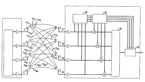
FIG. 2 presents a block diagram of a receiver in accord with the
25 principles of this invention. It includes a transmitter 10 that has an n
plurality of transmitting antenna 1, 2, 3, 4, and a receiver 20 that has an
m plurality of receiver antennas 21, 22, 23, 24. The signals received by
the receiver's antennas are multiplied in elements 25, 26, 27, and 28, and

CA 02255464 2001-07-10
4
summed in adder 30. More specifically, the received signal of antenna j
is multiplied by a value, ~,~ , and summed. The collection of factors ~,~
can be viewed as a vector A . The outputs of the receiver antennas are
also applied to processor 40 which, employing conventional techniques,
5 determines the transfer functions a~ for i=1, 2, 3,..., n and j=1, 2, 3,...,
m. These transfer functions can be evaluated, for example, through the
use of training sequences that are sent by the different transmitter
antennas, one antenna at a time.
The evaluated a;~ signals of processor 40 are applied to
10 processor 45 in FIG. 2 where the multiplier signals ~,~, j=l, 2, 3,..., m
are
computed. Processor 45 also evaluates a set of combined transfer
function values y; , i=1, 2, 3,..., n (which are described in more detail
below). Signals y; of processor 45 and the output signal of adder 30 are
applied to detector 50 which detects the transmitted symbols in
15 accordance with calculations disclosed below.
It is assumed that the symbols transmitted by the antennas of
transmitter 10 have been encoded in blocks of L time frames; and that
fading is constant within a frame. A codeword comprises all of the
symbols transmitted within a frame, and it corresponds, therefore, to
20 C~CZC3.. C4C~CZC3.. C4C~CZC3.. C4.. C~ CZ C3 .. C4
1 I 1 ' 1 2 2 2 ' 2 3 3 3 ' 3 ' m m m ' m~
where the superscript designates the transmitter's antennas and the
subscript designates the time of transmission (or position within a
frame).
From the standpoint of a single transmitting antenna, e.g., antenna
25 1, the signal that is received from antenna 1 in response to a transmitted
symbol crl at time interval t is:

CA 02255464 2001-07-10
5
Rr -Cr(alla'1 -~a12/~'2 -1-al3a'3 +...-~a,ml~,ur)
nr
C, ~ ~.j a,j
j=1
1
= Cr y1
(when noise is ignored). If each ~,j value is set to a *, j , (where a *,~ is
the complex conjugate of a,j ) then the received signal would simply be
nr
2
Rr = c~ ~~ali
.=1
5 yielding a constructive addition.
Of course, the values of ~,j cannot be set to match a *,j and
concurrently to match the values of a * ~ where i ~ 1; and therein lies the
difficulty.
When all n of the transmitting antennas are considered, then the
10 received signal is
n m
R~ _ ~ C~ ~'~la
=1 j=_I
n
= i
Cr yi
i=1
In accordance with the present disclosure, the objective is to
maximize ~ ly; IZ because by doing so, signal R, contains as much
r=1
information about c; , i =1,2,3,...n as is possible. However, it can be
15 easily shown that if a matrix A is constructed such that
n
A=~(~i*)''~r
i=1
where S2; _ (a;, , a; z , a; 3 ...a;", ) , then
r=1

CA 02255464 2001-07-10
6
The receiver, thus, has to maximize AA(A*)'~ , subject to the
constraint IIAlI2 =1. The solution to this problem is to choose A to be
the eigenvector of A which corresponds to the maximum eigenvalue of
A. Accordingly, processor 45 develops the matrix A from the values
5 ofa~ , finds the eigenvalues ofA in a conventional manner, selects the
maximum eigenvalue of A, and creates the vector A . Once A is known,
processor 45 develops signals y; for 1=1, 2, 3,..., n, (where
ni
y; _ ~~,ja~ ), and applies them to detector 50. Finally, detector 50
j=I
minimizes the metric
L n
10 ~ R, - ~ y; c;
from amongst all possible codewords in a conventional manner. As can
be seen, this approach reduces the complexity of decoding by almost a
factor of m.
FIG. 2 depicts separate multipliers to multiply received signals by
15 multiplication factors ~,; , and it depicts separate blocks for elements
30,
40, 45, and 50. It should be understood, however, that different
embodiments are also possible. For example, it is quite conventional to
incorporate all of the above-mentioned elements in a single special
purpose processor, or in a single stored program controlled processor (or
20 a small number of processors). Other modifications and improvements
may also be incorporated, without departing from the spirit and scope of
the invention, which is defined in the following claims.

Dessin représentatif
Une figure unique qui représente un dessin illustrant l'invention.
États administratifs

Pour une meilleure compréhension de l'état de la demande ou brevet qui figure sur cette page, la rubrique Mise en garde , et les descriptions de Brevet , États administratifs , Taxes périodiques et Historique des paiements devraient être consultées.

États administratifs

Titre Date
Date de délivrance prévu 2002-08-06
(22) Dépôt 1998-12-10
Requête d'examen 1998-12-10
(41) Mise à la disponibilité du public 1999-06-23
(45) Délivré 2002-08-06
Réputé périmé 2018-12-10

Historique d'abandonnement

Il n'y a pas d'historique d'abandonnement

Historique des paiements

Type de taxes Anniversaire Échéance Montant payé Date payée
Requête d'examen 400,00 $ 1998-12-10
Enregistrement de documents 100,00 $ 1998-12-10
Le dépôt d'une demande de brevet 300,00 $ 1998-12-10
Taxe de maintien en état - Demande - nouvelle loi 2 2000-12-11 100,00 $ 2000-09-27
Taxe de maintien en état - Demande - nouvelle loi 3 2001-12-10 100,00 $ 2001-10-03
Taxe finale 300,00 $ 2002-05-16
Taxe de maintien en état - brevet - nouvelle loi 4 2002-12-10 100,00 $ 2002-12-04
Taxe de maintien en état - brevet - nouvelle loi 5 2003-12-10 150,00 $ 2003-11-05
Taxe de maintien en état - brevet - nouvelle loi 6 2004-12-10 200,00 $ 2004-11-04
Taxe de maintien en état - brevet - nouvelle loi 7 2005-12-12 200,00 $ 2005-11-04
Taxe de maintien en état - brevet - nouvelle loi 8 2006-12-11 200,00 $ 2006-11-07
Taxe de maintien en état - brevet - nouvelle loi 9 2007-12-10 200,00 $ 2007-11-07
Taxe de maintien en état - brevet - nouvelle loi 10 2008-12-10 250,00 $ 2008-11-12
Taxe de maintien en état - brevet - nouvelle loi 11 2009-12-10 250,00 $ 2009-11-10
Taxe de maintien en état - brevet - nouvelle loi 12 2010-12-10 250,00 $ 2010-11-17
Taxe de maintien en état - brevet - nouvelle loi 13 2011-12-12 250,00 $ 2011-11-17
Taxe de maintien en état - brevet - nouvelle loi 14 2012-12-10 250,00 $ 2012-11-15
Taxe de maintien en état - brevet - nouvelle loi 15 2013-12-10 450,00 $ 2013-11-14
Taxe de maintien en état - brevet - nouvelle loi 16 2014-12-10 450,00 $ 2014-11-14
Taxe de maintien en état - brevet - nouvelle loi 17 2015-12-10 450,00 $ 2015-11-13
Taxe de maintien en état - brevet - nouvelle loi 18 2016-12-12 450,00 $ 2016-11-10
Titulaires au dossier

Les titulaires actuels et antérieures au dossier sont affichés en ordre alphabétique.

Titulaires actuels au dossier
AT&T WIRELESS SERVICES, INC.
Titulaires antérieures au dossier
LO, TITUS
TAROKH, VAHID
Les propriétaires antérieurs qui ne figurent pas dans la liste des « Propriétaires au dossier » apparaîtront dans d'autres documents au dossier.
Documents

Pour visionner les fichiers sélectionnés, entrer le code reCAPTCHA :


Pour visualiser une image, cliquer sur un lien dans la colonne description du document. Pour télécharger l'image (les images), cliquer l'une ou plusieurs cases à cocher dans la première colonne et ensuite cliquer sur le bouton "Télécharger sélection en format PDF (archive Zip)" ou le bouton "Télécharger sélection (en un fichier PDF fusionné)".

Liste des documents de brevet publiés et non publiés sur la BDBC .

Si vous avez des difficultés à accéder au contenu, veuillez communiquer avec le Centre de services à la clientèle au 1-866-997-1936, ou envoyer un courriel au Centre de service à la clientèle de l'OPIC.


Description du
Document 
Date
(yyyy-mm-dd) 
Nombre de pages   Taille de l'image (Ko) 
Page couverture 2002-07-02 1 44
Abrégé 1998-12-10 1 20
Description 1998-12-10 6 211
Revendications 1998-12-10 2 43
Dessins 1998-12-10 2 35
Description 2001-07-10 6 221
Revendications 2001-07-10 2 43
Page couverture 1999-07-08 1 41
Dessins représentatifs 1999-07-08 1 11
Dessins représentatifs 2002-07-02 1 12
Poursuite-Amendment 1999-02-26 3 71
Correspondance 2009-09-14 1 15
Correspondance 2009-09-14 1 16
Correspondance 2002-10-31 7 283
Poursuite-Amendment 2001-07-10 10 323
Poursuite-Amendment 2001-04-02 2 66
Correspondance 2002-05-16 1 35
Correspondance 2002-10-15 1 24
Cession 1998-12-10 6 185
Correspondance 2002-09-25 3 125
Correspondance 2002-10-15 1 13
Correspondance 2009-08-24 2 71