Language selection

Search

Patent 2256141 Summary

Third-party information liability

Some of the information on this Web page has been provided by external sources. The Government of Canada is not responsible for the accuracy, reliability or currency of the information supplied by external sources. Users wishing to rely upon this information should consult directly with the source of the information. Content provided by external sources is not subject to official languages, privacy and accessibility requirements.

Claims and Abstract availability

Any discrepancies in the text and image of the Claims and Abstract are due to differing posting times. Text of the Claims and Abstract are posted:

  • At the time the application is open to public inspection;
  • At the time of issue of the patent (grant).
(12) Patent Application: (11) CA 2256141
(54) English Title: COMPONENT MOUNTING ARRANGEMENT, CLIP AND ASSEMBLY
(54) French Title: SYSTEME D'INSTALLATION, PINCE ET ASSEMBLAGE D'UN ELEMENT
Status: Dead
Bibliographic Data
(51) International Patent Classification (IPC):
  • F16B 2/24 (2006.01)
  • F16B 5/06 (2006.01)
  • H01L 23/40 (2006.01)
  • H05K 7/20 (2006.01)
(72) Inventors :
  • PERSSON, MICHAEL (Sweden)
(73) Owners :
  • EMERSON ENERGY SYSTEMS AB (Not Available)
(71) Applicants :
  • TELEFONAKTIEBOLAGET LM ERICSSON (Sweden)
(74) Agent: MARKS & CLERK
(74) Associate agent:
(45) Issued:
(22) Filed Date: 1998-12-16
(41) Open to Public Inspection: 1999-06-17
Availability of licence: N/A
(25) Language of filing: English

Patent Cooperation Treaty (PCT): No

(30) Application Priority Data:
Application No. Country/Territory Date
9704719-5 Sweden 1997-12-17

Abstracts

English Abstract


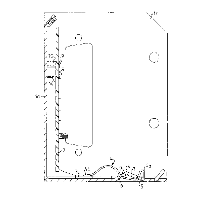
Heat-generating power transistors (3) hanging from a circuit board (2) are mounted
pressed flush against the inside surface of a heat dissipating thin sheet metal box
(1), by means of spring metal band clips (4) completely mountable from outside the
metal box (1), by insertion of a foot end (4b) of each clip into a first slot (6) in the
box and snapping an opposite end (4a), bent to form a spring fluke, into a second
parallel slot (5). Slots (6,5) and a clip resessing trough (7) between them can be
stamped in the thin sheet metal box. bottom (lb).


Claims

Note: Claims are shown in the official language in which they were submitted.


CLAIMS

1. Arrangement comprising:
a. a mounting element (1) having a first side and a second side;
b. a component to be mounted on the surface of the first side of the mounting
element;
c. a spring clip, having a first end (4b) and a second end (4a), and being disposed
for mounting the component continually pressed by spring force
against the first side of the mounting element; wherein,
the mounting element (1) is provided with at least one first slot (6) and at
least one second slot (5);
the spring clip is insertable with its first end (4b) into said first slot (6) in the
mounting element from the second side of the mounting element opposite the
component, until the component is sandwiched between the mounting element
(1) and said first end (4b);
the second opposite end (4a) of the spring clip is provided with hook means
(4a) for engagement in the second slot (5) from said second side, whereupon
the spring force of the spring clip continually presses the component against
the surface of the first side of the mounting element; and
said second side of the mounting element (1) is provided with a depression
intermediate said first and second slots (5,6), such that the spring clip, when
mounted in place, does not extend above the surface of said second side adjacentsaid depression.

2. Arrangement according to Claim 1, wherein the portion (4d) of the spring
clip (4) exposed on said second side of the mounting element (1), when
mounted in place, is completely contained within the depression.

3. Arrangement according to Claim 2, wherein a plurality of first slots (6) are
arranged in a first line and a plurality of second slots (5) are arranged in a
second line parallel thereto.


4. Arrangement according to Claim 3, wherein depressions between the first
and second slots (6,5) form a continuous trough (7) between the lines of slots.
5. Spring clip for mounting a component continually pressed against a
mounting element, comprising:
an elongated spring metal band having: at one end a foot (4b) insertable
through a first slot (6) in the mounting element (1) and adapted to press a
component against a surface of the mounting element, adjacent said foot a
spring arch (4c) and, at its end opposite said foot, a hook means (4a) for engagement,
from the side of the mounting element opposite the component, in
a second slot (5) in the mounting element (1).

6. Clip spring according to Claim 5, wherein said hook means is in the form
of a spring fluke, disposed to expand when said fully inserted into said second
slot (5).

7. Clip spring according to Claim 6, wherein the spring fluke is formed by
folding over the end (4a) of the spring metal band opposite the foot (4b).

8. Assembly comprising an arrangement as recited in one of Claims 1-4,
wherein heat generating components are appended to an electrical circuit
board (2), also mounted on the mounting element (1).

9. Assembly according to Claim 8, wherein said heat generating components
are transistor units (3).

10. Assembly according to Claim 8 or 9, wherein said mounting element (1) is
in turn intended for mounting flush against a heat absorbing chassis.

Description

Note: Descriptions are shown in the official language in which they were submitted.


CA 022~6141 1999-02-03


Component Mounting Arrangement Clip and Assembly

Technical Field of the Invention
The present invention relates to an arrangement for mounting a component or
5 components, to a spring clip, and to an assembly. The invention relates to
novel means for mounting heat-producing electrical components, such as
power transistors for example, in heat tr~ncmitt n~ flush abutment against a
heat dissipating metal mounting plate.

10 Description of Related Art
The present invention addresses problems arising when mounting heat gener-
ating electronic components. When mounting circuit boards in electronic
power units, the power transistors are connected h~nging from the board since
they generate excessive amounts of heat and must be cooled in some way.
15 Spring clips have been used to mount these heat generating power tr~ncictQrs
surface-to-surface (flush), with as much surface contact as possible, against a
mounting plate or box, to which the heat is transferred. Either a thin sheet
metal mounting plate/box or a thick cast-metal mounting base is used. In the
former case, the ~in sheet metal mounting plate/box conducts the heat rapidly
20 away, preferably to a heat absorbing and dissipating chassis on which it is
flush-mounted. In the latter case, the thick cast-metal mounting base acts as a
heat sink which has more capacity to absorb heat, but does not conduct the
heat away as rapidly as does the thin sheet metal box .

25 Various forms of spring clips have been used to hold the appended power
transistors pressed surface-to-surface (flush) against the surface of the
mounting box or mounting base. Examples of such previously known clips are
described in US-A 5 373 099, DE-A 42 18 224, US-A 5 343 362. and IBM
Technical Disclosure Bulletin, Vol. 24, No. lA, June 1981, page 226. These
30 spring clips and mounting boxes/bases have all been designed for mounting a
component, such as a transistor, against a side of a mounting base or plate

CA 022~6141 1999-02-03


from the component-side of the base and when this mounting base or plate is
the inside of a box, then the assembly worker must maneuver his or her fin-
gers inside the box, which is often very difficult due to the different compo-
nents within the box. The same problems arise when the spring clips are to be
5 removed.

A known method of mounting a row of spring clips is to place a bar over the
ends of all the spring clips remote from the power transistors, and hold this
bar in place using screws screwed in through the bottom of the box. This has
10 the disadvantage of having to m~m1~11y hold all the springs and the bar in
place while the screws are screwed in. Using screws, it is difficult, when us-
ing the t in sheet metal box favored for conducting heat rapidly away from
the power transistors, to prevent the screw heads from protruding beyond the
surface of the outside bottom of the box. Protruding screw heads prevent the
15 sheet metal box from being mounted flush against the heat absorbing çh~sic

The use of known spring clips with spring "flukes" or snap hooks at one or
both ends is described inter alia in the above mentioned IBM Technical Dis-
closure Bulletin Vol. 24, No. lA, June 1981, page 226, which describes a
20 two-legged, saddle-shaped mounting spring clip which straddles and fiImly
fixes a transistor against a mounting board by inserting the hooked ends of
the two legs, one end being folded over to form a spring fluke, into slots on
either side of the transistors. These clips give rise to the same problems as the
protruding screw heads since the hook ends of the spring clip protrude above
25 the surface of the outside bottom of the sheet metal box (in addition to the
difficulties involved with mounting from the inside as described above).


CA 022~6141 1999-02-03


Surnma~y of the Invention
These and other disadvantages of the prior art devices and arrangements are
removed by an arrangement, a clip and an assembly, respectively, of the types
described in the preambles to Claims 1,6 and 9 respectively, which have the
5 characterizing features recited in Claims 1, 6 and 9 respectively.

The arrangement, spring clip, and assembly according to the present inven-
tion permit easily m~nllf~ctured steel band spring clips to be mounted in place
and be removed without having to enter the box at all. This provides for easier
10 m~ml~l assembly or robotized assembly.

It is also possible to easily stamp the mounting plate of relatively thin sheet
metal with a trough and slots for the spring clips. This permits the assembled
box, clips and circuit board with appended transistors to be mounted flush
15 against a heat absorbing chassis.

Brief Description of the Drawin~s
Figs. lA - lD show the spring clip according to the invention.
Fig. 2a shows the mounting box alone.
20 Fig. 2b shows the mounting box 1 as seen from below.
Fig. 2c shows the assembly according to the invention comprising the
mounting box 1 provided with spring clips 4 (only one shown), pressing
power transistors 3 in place flush against the bottom portion lb of the
mounting box 1. The power transistors 3 hang down from a circuit board.
25 Figs. 3A-C show how the spring clip is inserted and snapped into place to
press the power transistor flush against the heat dissipating mounting box 1.


.. . ....

CA 022~6141 1999-02-03


Detailed Description of Embodiments
Fig. 1 shows one embodiment of a spring clip 4 according to the present in-
vention made of spring steel and having an arch 4c ending in a foot 4b with a
planar undersurface intended to press the heat-generating electronic compo-
5 nent against the surface of the box. The other end of the spring clip is pro-
vided with a V-spring fluke end 4a.

As can be seen in Figs. 2a-c, the mounting box 1 is made from a piece of
sheet metal folded to form a back la, a bottom lb and two end pieces lc. The
10 back la is designed to receive a pre-m~n-lf~ctured circuit board 2 which is
held in place by screws 9 screwed into threaded pedestals 10 in the back la.

As best can be seen in Fig. 2b (see also Figs 2a-b as well as Figs. 3A-C), the
bottom lb is provided with a trough 7 (forming a ridge on the inside of the
15 box). Slots 5, 6 are arranged on either side of the trough. The trough is created
by first ~ npillg out the sides slots 5,6 and two end slots 11 as well as a row
of holes 8 along the line where the bottom of the trough is to be. The slots andholes weaken the sheet metal at the right places for a proper trough to be
forrned when an elongated edge tool is pressed down along the row of holes
20 8.

Each of a series of spring clips 4 is inserted as shown sequentially in Figs.
3A-C. The foot 4b of the spring clip is inserted through the slot 6 closest to
the transistor 3. The clip is then pivoted as shown in Fig. 3B so that the foot
25 4b comes to rest on the transistor 3 and the V-spring fluke end 4a is inserted
into the slot 5 remote from the transistor. Pressure is applied until the fluke
snaps out to lock the spring clip in place, as shown in Fig. 3C. The spring
clip is held securely in place and each spring clip can be removed by com-
pressing the V-spring fluke end 4a.


CA 022~6141 1999-02-03


The person skilled in the art will readily recognize other means for fixing the
spring clip in place, such as a merely inserting an outwardly or inwardly bent
hook end of the clip into slot 5, although these embo(limmentc may not be as
secure.
s


This spring clip and the arrangement of which it is a part, thus provide an
easy method of pressing the power transistor surface-to-surface against the
heat tr~n~m~ ng thin sheet metal box. The spring clips can be mounted en-
tirely from the outside using robots, and, when mounted in place, the spring
10 clips do not protrude beyond the surface of the box, thereby m~kin~ it easy to
mount the box surface-to-surface against a heat absorbing chassis. The trough
with slots is also very easy to stamp in the thin sheet metal.


_ _

Representative Drawing
A single figure which represents the drawing illustrating the invention.
Administrative Status

For a clearer understanding of the status of the application/patent presented on this page, the site Disclaimer , as well as the definitions for Patent , Administrative Status , Maintenance Fee  and Payment History  should be consulted.

Administrative Status

Title Date
Forecasted Issue Date Unavailable
(22) Filed 1998-12-16
(41) Open to Public Inspection 1999-06-17
Dead Application 2002-12-16

Abandonment History

Abandonment Date Reason Reinstatement Date
2001-12-17 FAILURE TO PAY APPLICATION MAINTENANCE FEE

Payment History

Fee Type Anniversary Year Due Date Amount Paid Paid Date
Application Fee $300.00 1998-12-10
Registration of a document - section 124 $100.00 1998-12-16
Maintenance Fee - Application - New Act 2 2000-12-18 $100.00 2000-12-06
Registration of a document - section 124 $50.00 2001-02-07
Owners on Record

Note: Records showing the ownership history in alphabetical order.

Current Owners on Record
EMERSON ENERGY SYSTEMS AB
Past Owners on Record
PERSSON, MICHAEL
TELEFONAKTIEBOLAGET LM ERICSSON
Past Owners that do not appear in the "Owners on Record" listing will appear in other documentation within the application.
Documents

To view selected files, please enter reCAPTCHA code :


To view images, click a link in the Document Description column. To download the documents, select one or more checkboxes in the first column and then click the "Download Selected in PDF format (Zip Archive)" or the "Download Selected as Single PDF" button.

List of published and non-published patent-specific documents on the CPD .

If you have any difficulty accessing content, you can call the Client Service Centre at 1-866-997-1936 or send them an e-mail at CIPO Client Service Centre.


Document
Description 
Date
(yyyy-mm-dd) 
Number of pages   Size of Image (KB) 
Drawings 1998-12-16 7 103
Representative Drawing 1999-06-29 1 7
Description 1998-12-16 5 191
Abstract 1998-12-16 1 16
Claims 1998-12-16 2 76
Drawings 1999-02-03 7 103
Claims 1999-02-03 2 82
Abstract 1999-02-03 1 17
Cover Page 1999-06-29 1 32
Description 1999-02-03 5 204
Correspondence 1999-02-03 16 429
Correspondence 1999-01-26 1 24
Assignment 1998-12-16 4 124
Assignment 2001-02-07 26 1,351