Sélection de la langue

Search

Sommaire du brevet 2256141 

Énoncé de désistement de responsabilité concernant l'information provenant de tiers

Une partie des informations de ce site Web a été fournie par des sources externes. Le gouvernement du Canada n'assume aucune responsabilité concernant la précision, l'actualité ou la fiabilité des informations fournies par les sources externes. Les utilisateurs qui désirent employer cette information devraient consulter directement la source des informations. Le contenu fourni par les sources externes n'est pas assujetti aux exigences sur les langues officielles, la protection des renseignements personnels et l'accessibilité.

Disponibilité de l'Abrégé et des Revendications

L'apparition de différences dans le texte et l'image des Revendications et de l'Abrégé dépend du moment auquel le document est publié. Les textes des Revendications et de l'Abrégé sont affichés :

  • lorsque la demande peut être examinée par le public;
  • lorsque le brevet est émis (délivrance).
(12) Demande de brevet: (11) CA 2256141
(54) Titre français: SYSTEME D'INSTALLATION, PINCE ET ASSEMBLAGE D'UN ELEMENT
(54) Titre anglais: COMPONENT MOUNTING ARRANGEMENT, CLIP AND ASSEMBLY
Statut: Réputée abandonnée et au-delà du délai pour le rétablissement - en attente de la réponse à l’avis de communication rejetée
Données bibliographiques
(51) Classification internationale des brevets (CIB):
  • F16B 02/24 (2006.01)
  • F16B 05/06 (2006.01)
  • H01L 23/40 (2006.01)
  • H05K 07/20 (2006.01)
(72) Inventeurs :
  • PERSSON, MICHAEL (Suède)
(73) Titulaires :
  • EMERSON ENERGY SYSTEMS AB
(71) Demandeurs :
  • EMERSON ENERGY SYSTEMS AB (Suède)
(74) Agent: MARKS & CLERK
(74) Co-agent:
(45) Délivré:
(22) Date de dépôt: 1998-12-16
(41) Mise à la disponibilité du public: 1999-06-17
Licence disponible: S.O.
Cédé au domaine public: S.O.
(25) Langue des documents déposés: Anglais

Traité de coopération en matière de brevets (PCT): Non

(30) Données de priorité de la demande:
Numéro de la demande Pays / territoire Date
9704719-5 (Suède) 1997-12-17

Abrégés

Abrégé anglais


Heat-generating power transistors (3) hanging from a circuit board (2) are mounted
pressed flush against the inside surface of a heat dissipating thin sheet metal box
(1), by means of spring metal band clips (4) completely mountable from outside the
metal box (1), by insertion of a foot end (4b) of each clip into a first slot (6) in the
box and snapping an opposite end (4a), bent to form a spring fluke, into a second
parallel slot (5). Slots (6,5) and a clip resessing trough (7) between them can be
stamped in the thin sheet metal box. bottom (lb).

Revendications

Note : Les revendications sont présentées dans la langue officielle dans laquelle elles ont été soumises.


CLAIMS
1. Arrangement comprising:
a. a mounting element (1) having a first side and a second side;
b. a component to be mounted on the surface of the first side of the mounting
element;
c. a spring clip, having a first end (4b) and a second end (4a), and being disposed
for mounting the component continually pressed by spring force
against the first side of the mounting element; wherein,
the mounting element (1) is provided with at least one first slot (6) and at
least one second slot (5);
the spring clip is insertable with its first end (4b) into said first slot (6) in the
mounting element from the second side of the mounting element opposite the
component, until the component is sandwiched between the mounting element
(1) and said first end (4b);
the second opposite end (4a) of the spring clip is provided with hook means
(4a) for engagement in the second slot (5) from said second side, whereupon
the spring force of the spring clip continually presses the component against
the surface of the first side of the mounting element; and
said second side of the mounting element (1) is provided with a depression
intermediate said first and second slots (5,6), such that the spring clip, when
mounted in place, does not extend above the surface of said second side adjacentsaid depression.
2. Arrangement according to Claim 1, wherein the portion (4d) of the spring
clip (4) exposed on said second side of the mounting element (1), when
mounted in place, is completely contained within the depression.
3. Arrangement according to Claim 2, wherein a plurality of first slots (6) are
arranged in a first line and a plurality of second slots (5) are arranged in a
second line parallel thereto.

4. Arrangement according to Claim 3, wherein depressions between the first
and second slots (6,5) form a continuous trough (7) between the lines of slots.
5. Spring clip for mounting a component continually pressed against a
mounting element, comprising:
an elongated spring metal band having: at one end a foot (4b) insertable
through a first slot (6) in the mounting element (1) and adapted to press a
component against a surface of the mounting element, adjacent said foot a
spring arch (4c) and, at its end opposite said foot, a hook means (4a) for engagement,
from the side of the mounting element opposite the component, in
a second slot (5) in the mounting element (1).
6. Clip spring according to Claim 5, wherein said hook means is in the form
of a spring fluke, disposed to expand when said fully inserted into said second
slot (5).
7. Clip spring according to Claim 6, wherein the spring fluke is formed by
folding over the end (4a) of the spring metal band opposite the foot (4b).
8. Assembly comprising an arrangement as recited in one of Claims 1-4,
wherein heat generating components are appended to an electrical circuit
board (2), also mounted on the mounting element (1).
9. Assembly according to Claim 8, wherein said heat generating components
are transistor units (3).
10. Assembly according to Claim 8 or 9, wherein said mounting element (1) is
in turn intended for mounting flush against a heat absorbing chassis.

Description

Note : Les descriptions sont présentées dans la langue officielle dans laquelle elles ont été soumises.

CA 022~6141 1999-02-03
Component Mounting Arrangement Clip and Assembly
Technical Field of the Invention
The present invention relates to an arrangement for mounting a component or
5 components, to a spring clip, and to an assembly. The invention relates to
novel means for mounting heat-producing electrical components, such as
power transistors for example, in heat tr~ncmitt n~ flush abutment against a
heat dissipating metal mounting plate.
10 Description of Related Art
The present invention addresses problems arising when mounting heat gener-
ating electronic components. When mounting circuit boards in electronic
power units, the power transistors are connected h~nging from the board since
they generate excessive amounts of heat and must be cooled in some way.
15 Spring clips have been used to mount these heat generating power tr~ncictQrs
surface-to-surface (flush), with as much surface contact as possible, against a
mounting plate or box, to which the heat is transferred. Either a thin sheet
metal mounting plate/box or a thick cast-metal mounting base is used. In the
former case, the ~in sheet metal mounting plate/box conducts the heat rapidly
20 away, preferably to a heat absorbing and dissipating chassis on which it is
flush-mounted. In the latter case, the thick cast-metal mounting base acts as a
heat sink which has more capacity to absorb heat, but does not conduct the
heat away as rapidly as does the thin sheet metal box .
25 Various forms of spring clips have been used to hold the appended power
transistors pressed surface-to-surface (flush) against the surface of the
mounting box or mounting base. Examples of such previously known clips are
described in US-A 5 373 099, DE-A 42 18 224, US-A 5 343 362. and IBM
Technical Disclosure Bulletin, Vol. 24, No. lA, June 1981, page 226. These
30 spring clips and mounting boxes/bases have all been designed for mounting a
component, such as a transistor, against a side of a mounting base or plate

CA 022~6141 1999-02-03
from the component-side of the base and when this mounting base or plate is
the inside of a box, then the assembly worker must maneuver his or her fin-
gers inside the box, which is often very difficult due to the different compo-
nents within the box. The same problems arise when the spring clips are to be
5 removed.
A known method of mounting a row of spring clips is to place a bar over the
ends of all the spring clips remote from the power transistors, and hold this
bar in place using screws screwed in through the bottom of the box. This has
10 the disadvantage of having to m~m1~11y hold all the springs and the bar in
place while the screws are screwed in. Using screws, it is difficult, when us-
ing the t in sheet metal box favored for conducting heat rapidly away from
the power transistors, to prevent the screw heads from protruding beyond the
surface of the outside bottom of the box. Protruding screw heads prevent the
15 sheet metal box from being mounted flush against the heat absorbing çh~sic
The use of known spring clips with spring "flukes" or snap hooks at one or
both ends is described inter alia in the above mentioned IBM Technical Dis-
closure Bulletin Vol. 24, No. lA, June 1981, page 226, which describes a
20 two-legged, saddle-shaped mounting spring clip which straddles and fiImly
fixes a transistor against a mounting board by inserting the hooked ends of
the two legs, one end being folded over to form a spring fluke, into slots on
either side of the transistors. These clips give rise to the same problems as the
protruding screw heads since the hook ends of the spring clip protrude above
25 the surface of the outside bottom of the sheet metal box (in addition to the
difficulties involved with mounting from the inside as described above).

CA 022~6141 1999-02-03
Surnma~y of the Invention
These and other disadvantages of the prior art devices and arrangements are
removed by an arrangement, a clip and an assembly, respectively, of the types
described in the preambles to Claims 1,6 and 9 respectively, which have the
5 characterizing features recited in Claims 1, 6 and 9 respectively.
The arrangement, spring clip, and assembly according to the present inven-
tion permit easily m~nllf~ctured steel band spring clips to be mounted in place
and be removed without having to enter the box at all. This provides for easier
10 m~ml~l assembly or robotized assembly.
It is also possible to easily stamp the mounting plate of relatively thin sheet
metal with a trough and slots for the spring clips. This permits the assembled
box, clips and circuit board with appended transistors to be mounted flush
15 against a heat absorbing chassis.
Brief Description of the Drawin~s
Figs. lA - lD show the spring clip according to the invention.
Fig. 2a shows the mounting box alone.
20 Fig. 2b shows the mounting box 1 as seen from below.
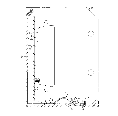
Fig. 2c shows the assembly according to the invention comprising the
mounting box 1 provided with spring clips 4 (only one shown), pressing
power transistors 3 in place flush against the bottom portion lb of the
mounting box 1. The power transistors 3 hang down from a circuit board.
25 Figs. 3A-C show how the spring clip is inserted and snapped into place to
press the power transistor flush against the heat dissipating mounting box 1.
.. . ....

CA 022~6141 1999-02-03
Detailed Description of Embodiments
Fig. 1 shows one embodiment of a spring clip 4 according to the present in-
vention made of spring steel and having an arch 4c ending in a foot 4b with a
planar undersurface intended to press the heat-generating electronic compo-
5 nent against the surface of the box. The other end of the spring clip is pro-
vided with a V-spring fluke end 4a.
As can be seen in Figs. 2a-c, the mounting box 1 is made from a piece of
sheet metal folded to form a back la, a bottom lb and two end pieces lc. The
10 back la is designed to receive a pre-m~n-lf~ctured circuit board 2 which is
held in place by screws 9 screwed into threaded pedestals 10 in the back la.
As best can be seen in Fig. 2b (see also Figs 2a-b as well as Figs. 3A-C), the
bottom lb is provided with a trough 7 (forming a ridge on the inside of the
15 box). Slots 5, 6 are arranged on either side of the trough. The trough is created
by first ~ npillg out the sides slots 5,6 and two end slots 11 as well as a row
of holes 8 along the line where the bottom of the trough is to be. The slots andholes weaken the sheet metal at the right places for a proper trough to be
forrned when an elongated edge tool is pressed down along the row of holes
20 8.
Each of a series of spring clips 4 is inserted as shown sequentially in Figs.
3A-C. The foot 4b of the spring clip is inserted through the slot 6 closest to
the transistor 3. The clip is then pivoted as shown in Fig. 3B so that the foot
25 4b comes to rest on the transistor 3 and the V-spring fluke end 4a is inserted
into the slot 5 remote from the transistor. Pressure is applied until the fluke
snaps out to lock the spring clip in place, as shown in Fig. 3C. The spring
clip is held securely in place and each spring clip can be removed by com-
pressing the V-spring fluke end 4a.

CA 022~6141 1999-02-03
The person skilled in the art will readily recognize other means for fixing the
spring clip in place, such as a merely inserting an outwardly or inwardly bent
hook end of the clip into slot 5, although these embo(limmentc may not be as
secure.
s
This spring clip and the arrangement of which it is a part, thus provide an
easy method of pressing the power transistor surface-to-surface against the
heat tr~n~m~ ng thin sheet metal box. The spring clips can be mounted en-
tirely from the outside using robots, and, when mounted in place, the spring
10 clips do not protrude beyond the surface of the box, thereby m~kin~ it easy to
mount the box surface-to-surface against a heat absorbing chassis. The trough
with slots is also very easy to stamp in the thin sheet metal.
_ _

Dessin représentatif
Une figure unique qui représente un dessin illustrant l'invention.
États administratifs

2024-08-01 : Dans le cadre de la transition vers les Brevets de nouvelle génération (BNG), la base de données sur les brevets canadiens (BDBC) contient désormais un Historique d'événement plus détaillé, qui reproduit le Journal des événements de notre nouvelle solution interne.

Veuillez noter que les événements débutant par « Inactive : » se réfèrent à des événements qui ne sont plus utilisés dans notre nouvelle solution interne.

Pour une meilleure compréhension de l'état de la demande ou brevet qui figure sur cette page, la rubrique Mise en garde , et les descriptions de Brevet , Historique d'événement , Taxes périodiques et Historique des paiements devraient être consultées.

Historique d'événement

Description Date
Le délai pour l'annulation est expiré 2002-12-16
Demande non rétablie avant l'échéance 2002-12-16
Réputée abandonnée - omission de répondre à un avis sur les taxes pour le maintien en état 2001-12-17
Lettre envoyée 2001-03-20
Inactive : Page couverture publiée 1999-06-29
Demande publiée (accessible au public) 1999-06-17
Inactive : CIB attribuée 1999-02-04
Inactive : CIB en 1re position 1999-02-04
Inactive : CIB attribuée 1999-02-04
Symbole de classement modifié 1999-02-04
Inactive : CIB attribuée 1999-02-04
Inactive : Correspondance - Formalités 1999-02-03
Demande reçue - nationale ordinaire 1999-01-20
Inactive : Certificat de dépôt - Sans RE (Anglais) 1999-01-20

Historique d'abandonnement

Date d'abandonnement Raison Date de rétablissement
2001-12-17

Taxes périodiques

Le dernier paiement a été reçu le 2000-12-06

Avis : Si le paiement en totalité n'a pas été reçu au plus tard à la date indiquée, une taxe supplémentaire peut être imposée, soit une des taxes suivantes :

  • taxe de rétablissement ;
  • taxe pour paiement en souffrance ; ou
  • taxe additionnelle pour le renversement d'une péremption réputée.

Les taxes sur les brevets sont ajustées au 1er janvier de chaque année. Les montants ci-dessus sont les montants actuels s'ils sont reçus au plus tard le 31 décembre de l'année en cours.
Veuillez vous référer à la page web des taxes sur les brevets de l'OPIC pour voir tous les montants actuels des taxes.

Historique des taxes

Type de taxes Anniversaire Échéance Date payée
Taxe pour le dépôt - générale 1998-12-16
Enregistrement d'un document 1998-12-16
TM (demande, 2e anniv.) - générale 02 2000-12-18 2000-12-06
Enregistrement d'un document 2001-02-07
Titulaires au dossier

Les titulaires actuels et antérieures au dossier sont affichés en ordre alphabétique.

Titulaires actuels au dossier
EMERSON ENERGY SYSTEMS AB
Titulaires antérieures au dossier
MICHAEL PERSSON
Les propriétaires antérieurs qui ne figurent pas dans la liste des « Propriétaires au dossier » apparaîtront dans d'autres documents au dossier.
Documents

Pour visionner les fichiers sélectionnés, entrer le code reCAPTCHA :


Pour visualiser une image, cliquer sur un lien dans la colonne description du document. Pour télécharger l'image (les images), cliquer l'une ou plusieurs cases à cocher dans la première colonne et ensuite cliquer sur le bouton "Télécharger sélection en format PDF (archive Zip)" ou le bouton "Télécharger sélection (en un fichier PDF fusionné)".

Liste des documents de brevet publiés et non publiés sur la BDBC .

Si vous avez des difficultés à accéder au contenu, veuillez communiquer avec le Centre de services à la clientèle au 1-866-997-1936, ou envoyer un courriel au Centre de service à la clientèle de l'OPIC.


Description du
Document 
Date
(aaaa-mm-jj) 
Nombre de pages   Taille de l'image (Ko) 
Dessin représentatif 1999-06-28 1 7
Description 1998-12-15 5 191
Abrégé 1998-12-15 1 16
Revendications 1998-12-15 2 76
Dessins 1998-12-15 7 103
Abrégé 1999-02-02 1 17
Description 1999-02-02 5 204
Revendications 1999-02-02 2 82
Dessins 1999-02-02 7 103
Courtoisie - Certificat d'enregistrement (document(s) connexe(s)) 1999-01-19 1 114
Certificat de dépôt (anglais) 1999-01-19 1 163
Rappel de taxe de maintien due 2000-08-16 1 110
Courtoisie - Lettre d'abandon (taxe de maintien en état) 2002-01-13 1 182
Correspondance 1999-01-25 1 24
Correspondance 1999-02-02 16 431