Language selection

Search

Patent 2261471 Summary

Third-party information liability

Some of the information on this Web page has been provided by external sources. The Government of Canada is not responsible for the accuracy, reliability or currency of the information supplied by external sources. Users wishing to rely upon this information should consult directly with the source of the information. Content provided by external sources is not subject to official languages, privacy and accessibility requirements.

Claims and Abstract availability

Any discrepancies in the text and image of the Claims and Abstract are due to differing posting times. Text of the Claims and Abstract are posted:

  • At the time the application is open to public inspection;
  • At the time of issue of the patent (grant).
(12) Patent Application: (11) CA 2261471
(54) English Title: CORNER TIE FOR CONCRETE POURING FORMS
(54) French Title: GOUSSET D'ANGLE POUR COFFRAGES DE COULAGE DU BETON
Status: Dead
Bibliographic Data
(51) International Patent Classification (IPC):
  • E04G 17/07 (2006.01)
  • E04G 17/00 (2006.01)
(72) Inventors :
  • MEENDERING, ALLEN (United States of America)
(73) Owners :
  • MEENDERING, ALLEN (United States of America)
(71) Applicants :
  • MEENDERING, ALLEN (United States of America)
(74) Agent: MACRAE & CO.
(74) Associate agent:
(45) Issued:
(22) Filed Date: 1999-02-11
(41) Open to Public Inspection: 2000-06-22
Availability of licence: N/A
(25) Language of filing: English

Patent Cooperation Treaty (PCT): No

(30) Application Priority Data:
Application No. Country/Territory Date
222,177 United States of America 1998-12-22

Abstracts

English Abstract


A bracket for use with a system of forms for holding poured concrete
forming concrete walls. The bracket is used to hold the forms at corners of
the system when the concrete walls change directions. The corner bracket
includes formations to hold the wall panels in place at the corner.


Claims

Note: Claims are shown in the official language in which they were submitted.


Claims
1. For use as a system of assembled walls for forms holding poured
concrete, said system including panels held in place by rails having flanges
joined together by a web to form a channel for the said panels, a bracket for
forming a corner in said system comprising bracket rails having cross sections
substantially similar to said first named rails, said bracket rails being set
at an angle to each other, and means formed on said flanges of said bracket
rails adapted to be pressed into said panels for resisting sliding of said
panels in said bracket rails.
2. The bracket of claim 1 in which said bracket rails have flanges
joined by a web in the same form as said first named rails, said flanges being
spaced apart in substantially parallel relationship from each other a distance
to closely embrace said panel.
3. The bracket of claim 2 in which said means for resisting sliding
includes ridges formed on said flanges in position to engage said panels.
4. The bracket of claim 2 in which there are at least four ridges on
each web of each of said bracket rails.
5. The bracket of claim 3 in which said flanges are parallel and have
facing surfaces.
6. The bracket of claim 5 in which said ridges are formed on both of
said facing surfaces.
7. The bracket of claim 1 in which brace means extends between said
bracket rails for holding said bracket rails in said angular relationship.
4

Description

Note: Descriptions are shown in the official language in which they were submitted.


CA 02261471 1999-02-11
TITLE: Corner Tie for Concrete Pouring Forms
BACKGROUND AND SUMMARY OF THE INVENTION
This invention pertains to systems of spaced apart walls providing space
into which concrete can be poured to form a concrete wall. Such systems are
shown and fully described in applicant's co-pending application Serial
#2,219,414, filed October 24, 1997. Briefly those forms include panels held
together by H-shaped tracks to assemble walls for the forms. The walls are
then held in substantially parallel relationships by some form of tie member
engaged between the parallel walls. These ties are frequently associated with
the tracks that hold the panels.
Such systems work well for straight walls. At corners, however, there
are frequently problems. Corners in this sense are commonly right angle
intersections, but may be less or more than a 90 degree intersection.
Further, a corner for the purpose of this application may be a rounded corner
as well as a sharp angular intersection.
At such corner, it is fairly common for the panels of plastic forming
the wall section to be pulled apart, thus separating the panel from the rails.
This is particularly true of the outer wall at the corner, though the inner
wall, too, may separate.
By this invention, a rail combination forming the corner of the wall is
formed with gripping parts which have a strong tendency to hold the panel
piece in the rail and therefore to prevent separation at the corners.
BRIEF DESCRIPTION OF FIGURES
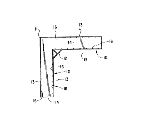
Figure 1 is a top plan view of the corner rail piece;
Figure 2 in an elevational view of the rail piece shown in Figure 1; and
Figure 3 in a sectional view from line 3-3 of Figure 2 and to an
enlarged scale.
1

CA 02261471 1999-02-11
DESCRIPTION
Briefly this invention comprises a pair of rails, joined at an
intersection to hold formed plastic panels in a corner formation. The panels
are used to hold concrete being poured to form a wall. The corner sections
are formed to provide ribs substantially perpendicular to the line of the wall
being poured so that the panels will be held in place in the rail as the
pouring process proceeds.
More specifically and referring to the drawings, the corner bracket is
formed of two rails 10 intersecting at a corner 11. A brace 12 may be used to
reinforce the corner. This brace may also be used as a material injection
point. As described in the co-pending application noted herein before, and as
shown on Figure 3, each rail is composed of a pair of flanges 13 joined
together by a web 14 forming an H-shape - or in case of a top or bottom rail -
a U-shape.
Although the bracket is illustrated as being for a right-angle corner,
it will be obvious that for odd-shaped (triangular, hexagonal, octagonal)
enclosures, or for offsets at other than a right angle, other brackets might
be built using proper angles for such other shapes. If panels can be formed
to fit a rounded corner, even that shape could be built into the corner
bracket.
The particularly unique factor of the bracket is the mechanism used to
prevent the sliding of a panel out of the bracket. On the inside wall of each
flange 13 are a series of ridges 16 disposed nearly perpendicular to the
web 14. These ridges must be pressed into the side of the panel forming the
wall as the form is assembled. They then form pairs of mating tongues on the
flanges 13 and groove formations pressed into the material of the panel which
resist any sliding of the panel relative to the bracket. This resistance is
2

CA 02261471 1999-02-11
ordinarily adequate to hold the panel in place in the bracket.
The use of multiple ridges is generally required because the ridge must
not be so high that assembly of the panel becomes difficult. Thus by using a
plurality of smaller ridges, the same effect as a higher ridge can be
achieved. It will be seen that in order to be effective, each bracket rail
must be of sufficient length to allow for the plurality of ridges. Experience
has shown that five or six or more ridges spaced apart approximately a half
to three quarters of the width of the web may be the minimum required in order
to be effective.
It is apparent that the invention makes feasible the use of a built up
form for the pouring of concrete by holding the form together at its corners
as well as along the straight part of the wall.
3
Representative Drawing
A single figure which represents the drawing illustrating the invention.
Administrative Status

For a clearer understanding of the status of the application/patent presented on this page, the site Disclaimer , as well as the definitions for Patent , Administrative Status , Maintenance Fee  and Payment History  should be consulted.

Administrative Status

Title Date
Forecasted Issue Date Unavailable
(22) Filed 1999-02-11
(41) Open to Public Inspection 2000-06-22
Dead Application 2004-02-11

Abandonment History

Abandonment Date Reason Reinstatement Date
2001-02-12 FAILURE TO PAY APPLICATION MAINTENANCE FEE 2001-03-21
2003-02-11 FAILURE TO PAY APPLICATION MAINTENANCE FEE

Payment History

Fee Type Anniversary Year Due Date Amount Paid Paid Date
Application Fee $150.00 1999-02-11
Reinstatement: Failure to Pay Application Maintenance Fees $200.00 2001-03-21
Maintenance Fee - Application - New Act 2 2001-02-12 $50.00 2001-03-21
Maintenance Fee - Application - New Act 3 2002-02-11 $50.00 2002-02-11
Owners on Record

Note: Records showing the ownership history in alphabetical order.

Current Owners on Record
MEENDERING, ALLEN
Past Owners on Record
None
Past Owners that do not appear in the "Owners on Record" listing will appear in other documentation within the application.
Documents

To view selected files, please enter reCAPTCHA code :


To view images, click a link in the Document Description column. To download the documents, select one or more checkboxes in the first column and then click the "Download Selected in PDF format (Zip Archive)" or the "Download Selected as Single PDF" button.

List of published and non-published patent-specific documents on the CPD .

If you have any difficulty accessing content, you can call the Client Service Centre at 1-866-997-1936 or send them an e-mail at CIPO Client Service Centre.


Document
Description 
Date
(yyyy-mm-dd) 
Number of pages   Size of Image (KB) 
Representative Drawing 2000-06-15 1 5
Cover Page 2000-06-15 1 23
Abstract 1999-02-11 1 8
Claims 1999-02-11 1 30
Description 1999-02-11 3 92
Drawings 1999-02-11 1 13
Assignment 1999-02-11 3 67
Fees 2001-03-21 1 39