Sélection de la langue

Search

Sommaire du brevet 2261471 

Énoncé de désistement de responsabilité concernant l'information provenant de tiers

Une partie des informations de ce site Web a été fournie par des sources externes. Le gouvernement du Canada n'assume aucune responsabilité concernant la précision, l'actualité ou la fiabilité des informations fournies par les sources externes. Les utilisateurs qui désirent employer cette information devraient consulter directement la source des informations. Le contenu fourni par les sources externes n'est pas assujetti aux exigences sur les langues officielles, la protection des renseignements personnels et l'accessibilité.

Disponibilité de l'Abrégé et des Revendications

L'apparition de différences dans le texte et l'image des Revendications et de l'Abrégé dépend du moment auquel le document est publié. Les textes des Revendications et de l'Abrégé sont affichés :

  • lorsque la demande peut être examinée par le public;
  • lorsque le brevet est émis (délivrance).
(12) Demande de brevet: (11) CA 2261471
(54) Titre français: GOUSSET D'ANGLE POUR COFFRAGES DE COULAGE DU BETON
(54) Titre anglais: CORNER TIE FOR CONCRETE POURING FORMS
Statut: Morte
Données bibliographiques
(51) Classification internationale des brevets (CIB):
  • E04G 17/07 (2006.01)
  • E04G 17/00 (2006.01)
(72) Inventeurs :
  • MEENDERING, ALLEN (Etats-Unis d'Amérique)
(73) Titulaires :
  • MEENDERING, ALLEN (Etats-Unis d'Amérique)
(71) Demandeurs :
  • MEENDERING, ALLEN (Etats-Unis d'Amérique)
(74) Agent: MACRAE & CO.
(74) Co-agent:
(45) Délivré:
(22) Date de dépôt: 1999-02-11
(41) Mise à la disponibilité du public: 2000-06-22
Licence disponible: S.O.
(25) Langue des documents déposés: Anglais

Traité de coopération en matière de brevets (PCT): Non

(30) Données de priorité de la demande:
Numéro de la demande Pays / territoire Date
222,177 Etats-Unis d'Amérique 1998-12-22

Abrégés

Abrégé anglais


A bracket for use with a system of forms for holding poured concrete
forming concrete walls. The bracket is used to hold the forms at corners of
the system when the concrete walls change directions. The corner bracket
includes formations to hold the wall panels in place at the corner.

Revendications

Note : Les revendications sont présentées dans la langue officielle dans laquelle elles ont été soumises.


Claims
1. For use as a system of assembled walls for forms holding poured
concrete, said system including panels held in place by rails having flanges
joined together by a web to form a channel for the said panels, a bracket for
forming a corner in said system comprising bracket rails having cross sections
substantially similar to said first named rails, said bracket rails being set
at an angle to each other, and means formed on said flanges of said bracket
rails adapted to be pressed into said panels for resisting sliding of said
panels in said bracket rails.
2. The bracket of claim 1 in which said bracket rails have flanges
joined by a web in the same form as said first named rails, said flanges being
spaced apart in substantially parallel relationship from each other a distance
to closely embrace said panel.
3. The bracket of claim 2 in which said means for resisting sliding
includes ridges formed on said flanges in position to engage said panels.
4. The bracket of claim 2 in which there are at least four ridges on
each web of each of said bracket rails.
5. The bracket of claim 3 in which said flanges are parallel and have
facing surfaces.
6. The bracket of claim 5 in which said ridges are formed on both of
said facing surfaces.
7. The bracket of claim 1 in which brace means extends between said
bracket rails for holding said bracket rails in said angular relationship.
4

Description

Note : Les descriptions sont présentées dans la langue officielle dans laquelle elles ont été soumises.


CA 02261471 1999-02-11
TITLE: Corner Tie for Concrete Pouring Forms
BACKGROUND AND SUMMARY OF THE INVENTION
This invention pertains to systems of spaced apart walls providing space
into which concrete can be poured to form a concrete wall. Such systems are
shown and fully described in applicant's co-pending application Serial
#2,219,414, filed October 24, 1997. Briefly those forms include panels held
together by H-shaped tracks to assemble walls for the forms. The walls are
then held in substantially parallel relationships by some form of tie member
engaged between the parallel walls. These ties are frequently associated with
the tracks that hold the panels.
Such systems work well for straight walls. At corners, however, there
are frequently problems. Corners in this sense are commonly right angle
intersections, but may be less or more than a 90 degree intersection.
Further, a corner for the purpose of this application may be a rounded corner
as well as a sharp angular intersection.
At such corner, it is fairly common for the panels of plastic forming
the wall section to be pulled apart, thus separating the panel from the rails.
This is particularly true of the outer wall at the corner, though the inner
wall, too, may separate.
By this invention, a rail combination forming the corner of the wall is
formed with gripping parts which have a strong tendency to hold the panel
piece in the rail and therefore to prevent separation at the corners.
BRIEF DESCRIPTION OF FIGURES
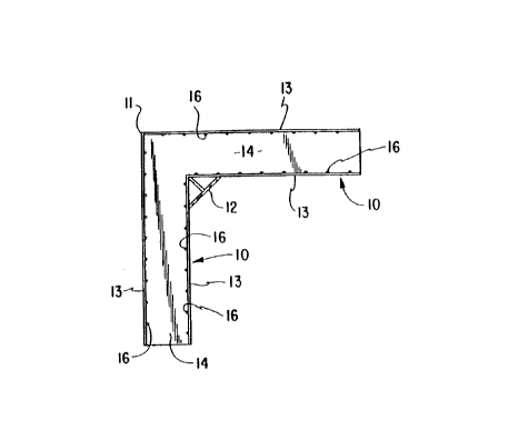
Figure 1 is a top plan view of the corner rail piece;
Figure 2 in an elevational view of the rail piece shown in Figure 1; and
Figure 3 in a sectional view from line 3-3 of Figure 2 and to an
enlarged scale.
1

CA 02261471 1999-02-11
DESCRIPTION
Briefly this invention comprises a pair of rails, joined at an
intersection to hold formed plastic panels in a corner formation. The panels
are used to hold concrete being poured to form a wall. The corner sections
are formed to provide ribs substantially perpendicular to the line of the wall
being poured so that the panels will be held in place in the rail as the
pouring process proceeds.
More specifically and referring to the drawings, the corner bracket is
formed of two rails 10 intersecting at a corner 11. A brace 12 may be used to
reinforce the corner. This brace may also be used as a material injection
point. As described in the co-pending application noted herein before, and as
shown on Figure 3, each rail is composed of a pair of flanges 13 joined
together by a web 14 forming an H-shape - or in case of a top or bottom rail -
a U-shape.
Although the bracket is illustrated as being for a right-angle corner,
it will be obvious that for odd-shaped (triangular, hexagonal, octagonal)
enclosures, or for offsets at other than a right angle, other brackets might
be built using proper angles for such other shapes. If panels can be formed
to fit a rounded corner, even that shape could be built into the corner
bracket.
The particularly unique factor of the bracket is the mechanism used to
prevent the sliding of a panel out of the bracket. On the inside wall of each
flange 13 are a series of ridges 16 disposed nearly perpendicular to the
web 14. These ridges must be pressed into the side of the panel forming the
wall as the form is assembled. They then form pairs of mating tongues on the
flanges 13 and groove formations pressed into the material of the panel which
resist any sliding of the panel relative to the bracket. This resistance is
2

CA 02261471 1999-02-11
ordinarily adequate to hold the panel in place in the bracket.
The use of multiple ridges is generally required because the ridge must
not be so high that assembly of the panel becomes difficult. Thus by using a
plurality of smaller ridges, the same effect as a higher ridge can be
achieved. It will be seen that in order to be effective, each bracket rail
must be of sufficient length to allow for the plurality of ridges. Experience
has shown that five or six or more ridges spaced apart approximately a half
to three quarters of the width of the web may be the minimum required in order
to be effective.
It is apparent that the invention makes feasible the use of a built up
form for the pouring of concrete by holding the form together at its corners
as well as along the straight part of the wall.
3
Dessin représentatif
Une figure unique qui représente un dessin illustrant l'invention.
États administratifs

Pour une meilleure compréhension de l'état de la demande ou brevet qui figure sur cette page, la rubrique Mise en garde , et les descriptions de Brevet , États administratifs , Taxes périodiques et Historique des paiements devraient être consultées.

États administratifs

Titre Date
Date de délivrance prévu Non disponible
(22) Dépôt 1999-02-11
(41) Mise à la disponibilité du public 2000-06-22
Demande morte 2004-02-11

Historique d'abandonnement

Date d'abandonnement Raison Reinstatement Date
2001-02-12 Taxe périodique sur la demande impayée 2001-03-21
2003-02-11 Taxe périodique sur la demande impayée

Historique des paiements

Type de taxes Anniversaire Échéance Montant payé Date payée
Le dépôt d'une demande de brevet 150,00 $ 1999-02-11
Rétablissement: taxe de maintien en état non-payées pour la demande 200,00 $ 2001-03-21
Taxe de maintien en état - Demande - nouvelle loi 2 2001-02-12 50,00 $ 2001-03-21
Taxe de maintien en état - Demande - nouvelle loi 3 2002-02-11 50,00 $ 2002-02-11
Titulaires au dossier

Les titulaires actuels et antérieures au dossier sont affichés en ordre alphabétique.

Titulaires actuels au dossier
MEENDERING, ALLEN
Titulaires antérieures au dossier
S.O.
Les propriétaires antérieurs qui ne figurent pas dans la liste des « Propriétaires au dossier » apparaîtront dans d'autres documents au dossier.
Documents

Pour visionner les fichiers sélectionnés, entrer le code reCAPTCHA :


Pour visualiser une image, cliquer sur un lien dans la colonne description du document. Pour télécharger l'image (les images), cliquer l'une ou plusieurs cases à cocher dans la première colonne et ensuite cliquer sur le bouton "Télécharger sélection en format PDF (archive Zip)" ou le bouton "Télécharger sélection (en un fichier PDF fusionné)".

Liste des documents de brevet publiés et non publiés sur la BDBC .

Si vous avez des difficultés à accéder au contenu, veuillez communiquer avec le Centre de services à la clientèle au 1-866-997-1936, ou envoyer un courriel au Centre de service à la clientèle de l'OPIC.


Description du
Document 
Date
(yyyy-mm-dd) 
Nombre de pages   Taille de l'image (Ko) 
Dessins représentatifs 2000-06-15 1 5
Page couverture 2000-06-15 1 23
Abrégé 1999-02-11 1 8
Revendications 1999-02-11 1 30
Description 1999-02-11 3 92
Dessins 1999-02-11 1 13
Cession 1999-02-11 3 67
Taxes 2001-03-21 1 39