Language selection

Search

Patent 2261511 Summary

Third-party information liability

Some of the information on this Web page has been provided by external sources. The Government of Canada is not responsible for the accuracy, reliability or currency of the information supplied by external sources. Users wishing to rely upon this information should consult directly with the source of the information. Content provided by external sources is not subject to official languages, privacy and accessibility requirements.

Claims and Abstract availability

Any discrepancies in the text and image of the Claims and Abstract are due to differing posting times. Text of the Claims and Abstract are posted:

  • At the time the application is open to public inspection;
  • At the time of issue of the patent (grant).
(12) Patent: (11) CA 2261511
(54) English Title: DOOR LOCK DEVICE
(54) French Title: DISPOSITIF DE VERROUILLAGE DE PORTE
Status: Deemed expired
Bibliographic Data
(51) International Patent Classification (IPC):
  • E05C 1/14 (2006.01)
  • E05B 9/08 (2006.01)
  • E05B 17/04 (2006.01)
  • E05B 55/00 (2006.01)
  • E05B 63/08 (2006.01)
  • E05B 9/04 (2006.01)
  • E05B 17/20 (2006.01)
(72) Inventors :
  • LIANG, CHIA PEL (Taiwan, Province of China)
(73) Owners :
  • LIANG, CHIA PEL (Taiwan, Province of China)
(71) Applicants :
  • LIANG, CHIA PEL (Taiwan, Province of China)
(74) Agent: CASSAN MACLEAN
(74) Associate agent:
(45) Issued: 2003-06-03
(22) Filed Date: 1999-02-12
(41) Open to Public Inspection: 2000-08-12
Examination requested: 1999-02-12
Availability of licence: N/A
(25) Language of filing: English

Patent Cooperation Treaty (PCT): No

(30) Application Priority Data: None

Abstracts

English Abstract


A door lock device is disposed on a door 1. The door 1
has an upper through hole 11 and a lower through hole 12.
The door lock device has a latch bolt device 6 disposed on
the door 1, a case frame 2 having an upper hollow cylinder
22 inserted through the upper through hole 11 and a lower
hollow cylinder 23 inserted through the lower through hole
12, a first pressing plate 8 disposed on the case frame 2,
a core 3 disposed in the upper hollow cylinder 22, a lock
fastener device 4 disposed in the upper hollow cylinder 22,
and a drive mechanism 5 disposed in the upper hollow
cylinder 22. The drive mechanism 5 has a rack 53 to drive
the latch bolt device 6. A locking plate 71 covers the
upper through hole 11 and the lower through hole 12. A
decoration plate 72 is disposed on the locking plate 71.
A second pressing plate 8' is disposed on the decoration
plate 72.


Claims

Note: Claims are shown in the official language in which they were submitted.


I CLAIM:

1. A door lock device disposed on a door 1, the door
having an upper through hole 11 and a lower through hole
12, the door lock device comprising a latch bolt device 6
disposed on the door 1, a case frame 2 having an upper
hollow cylinder 22 inserted through the upper through
hole 11 and a lower hollow cylinder 23 inserted through
the lower through hole 12, a first pressing plate 8
disposed on the case frame 2, and a drive mechanism 5
disposed in the upper hollow cylinder 22, characterized
in that:
the case frame 2 further has a recess 21,
a core 3 has a driven block 31,
a lock fastener device 4 has a lateral elastic block
42 and a blocking bar 41,
the upper hollow cylinder 22 has an inner groove
222, a lateral slot 221, and a core seat 223 receiving
the core 3 and the lock fastener device 4,
the core seat 223 has a bottom hole 224,
the drive mechanism 5 has a rack 53 to drive the
latch bolt device 6, and a drive frame 51 having a gear
set 52 to drive the rack 53,
the rack 53 has an upper groove 532 and an end
groove 531,
the rack 53 passes through the lateral slot 221 to
connect to the latch bolt device 6,
7


a pressing device 81' is disposed in the upper
hollow cylinder 22 to connect to the drive frame 51,
the pressing device 81' has a protruded block 82',
the blocking bar 41 is inserted in the end groove 531,
a compression spring S is disposed between the drive
frame 51 and the rack 53,
a torsion spring S1 is disposed between the core 3
and the lock fastener device 4,
the first pressing plate 8 has an upper pressing
portion 81,
the recess 21 receives the first pressing plate 8,
a locking plate 71 covers the upper through hole 11
and the lower through hole 12,
a decoration plate 72 is disposed on the locking
plate 71,
the decoration plate 72 has an opening 73,
a second pressing plate 8' is disposed on the
decoration plate 72,
the opening 73 receives the second pressing plate 8',
and
an upper portion of the second pressing plate 8' is
connected to the pressing device 81'.
2. A door lock device as claimed in claim 1, wherein
a connection frame 92 is disposed between the upper
portion of the second pressing plate 8' and the pressing

8


device 81', and a link 91 has a first end connected to
the connection frame 92 and a second end connected to the
second pressing plate 8'.


9

Description

Note: Descriptions are shown in the official language in which they were submitted.


CA 02261511 1999-02-12
TITLE: DOOR LOCK DEVICE
The present invention relates to a door Iock device.
More particularly, the present invention relates to a
door lock device which is detached easily.
A conventional door lock device has a dead bolt and
05 a latch bolt. However, the latch bolt will block a door
while. the door is opened. Furthermore, a doorknob is
often protruded from an otter face of the door. Thus a
child may bump the doorknob accidentally. If a core of
the conventional door lock device is broken, the whole
door lock device should be replaced.
An object of the present invention is to provide
a door lock device which can be disassembled easily. Thus
a core of the door lock device can be replaced easily.
Another object of the present invention is to
provide a door lock device which has a case frame
having an upper hollow cylinder inserted through an upper
thxough hole of a door and a lower hollow cylinder
inserted through a Iower through hole of the door so that
an outer face of the case frame can contact an Outer face
of the door flatly.
Another object of the present invention is to
provide a door lock device which has a drive mechanism
having a rack to drive a latch bolt device so that the
latch bolt device will not block a door while the door
is opened.
1

CA 02261511 1999-02-12
Another object of the present invention is to
provide a door lock device which has a torsion spring
to force a first pressing plate contacting a case frame
while the first pressing plate is not operated.
05 FIG. 1 is a perspective exploded view of a door lock
device of a preferred embodiment in accordance with the
present invention;
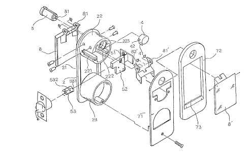
FIG. 2 is a perspective exploded view of a case
frame, a latch bolt device, a decoration plate, and a
pressing plate;
FIG. 3A is a schematic view illustrating an engage-
ment of a latch bolt device and a drive mechanism;
FIG. 3B is another schematic view illustrating an
engagement of a latch bolt device and a drive mechanism;
I5 FIG. 4A is a schematic view illustrating an appli-
cation of a door lock device while the door lock device
is locked;
FIG. 4B is a schematic view illustrating an appli
cation of a door lock device while the door lock device
is unlocked;
FIG. 5 is a schematic view illustrating an engage-
ment of a protruded block of a pressing device and an
elastic block of a lock fastener device;
FIG. 6A is a schematic view illustrating a first
pressing plate disposed on a case frame while the first
2

CA 02261511 1999-02-12
pressing plate is not operated;
FIG. 6B is a schematic view illustrating a drive
mechanism driving a latch bolt device to extend;
FIG. 7A is a schematic view illustrating a first
05 pressing plate disposed on a case frame while the first
press~.ng plate is operated;
FIG. 7B is a schematic view illustrating a drive
mechanism driving a latch bolt device to retract;
FIG. $ is a perspective exploded view of a door lock
device of another preferred embodiment in accordance with
the present invention; and
FIG. 9 is a schematic view illustrating an appli-
cation of a door lock device of another preferred embodi-
ment in accordance with the present invention.
Referring to FIGS. 1 to 7B, a door lock device is
disposed on a door 1. The door 1 has an upper through
hole 11 and a lower through hole 12. The door lock
device comprises a latch bolt device 6 disposed on the
door 1, a case frame 2 having an upper hollow cylinder 22
inserted through the upper through hole 11 and a lower
hollow cylinder 23 inserted through the lower through
hole 12, a first pressing plate 8 disposed on the
case frame 2, and a drive mechanism 5 disposed in the
upper holldw cylinder 22.
The case frame 2 further has a recess 21.
3

CA 02261511 1999-02-12
A core 3 has a driven block 31.
A lock fastener device 4 has a lateral elastic block
42 and a blocking bar 41.
The upper hollow cylinder 22 has an inner groove
05 222, a lateral slot 221, and a core seat 223 receiving
the core 3 and the lock fastener device 4. The core seat
223 has a bottom hole 224.
The drive mechanism 5 has a rack 53 to drive the
latch bolt device 6, and a drive frame 51 having a gear
set 52 to drive the rack 53. The rack 53 has an upper
groove 532 and an end groove 531. The rack 53 passes
through the lateral slot 221 to connect to the latch bolt
device 6. A pressing device 81' is disposed in the upper
hollow cylinder 22 to connect to the drive frame 51. The
pressing device 81' has a protruded block 82'.
The blocking bar 41 is inserted in the end groove 531.
A compression spring S is disposed between the drive frame
51 and the rack 53. A torsion spring S1 is disposed
between the core 3 and the lock fastener device 4.
The first pressing plate 8 has an upper pressing
portion 81. The recess 21 receives the first pressing
plate 8.
A locking plate 71 covers the upper through hole 11
and the lower through hole 12.
A decoration plate 72 is disposed on thd locking
4

CA 02261511 1999-02-12
plate 71. The decoration plate 72 has an opening 73. A
second pressing plate 8' is disposed on the decoration
plate 72. The opening 73 receives the second pressing
plate 8'. An upper portion of the second pressing plate 8'
05 is connected to the pressing device 81'.
The compression spring S pushes the latch bolt device
6 to extend (as shown in FIG. 3A). When the compression
spring S is compressed, the Latch bolt device 6 retracts
(as shown in FIG. 38).
20 Referring to FIG. 6B, the blocking bar 41 is inserted
in the end groove 531. The lateral elastic block 42 is
inserted in the bottom hole 224 (as shown in FIG. 4A).
Since the blocking bar 41 is inserted in the end groove
531, the latch bolt device 6 locks the door 1.
I5 When the second pressing plate 8' is operated, the
protruded block 82' contacts the lateral elastic block 42
to force the lateral elastic block 42 to retract (as
shown in FIG. 5). When the core 3 is rotated to contact
the lateral elastic block 42, the core 3 forces the
20 lateral elastic block 42 to retract.
When the lateral elastic block 42 disengages from
the bottom hole 224, the torsion spring S1 pushes the
lateral elastic block 42 to move (as shown in FIG. 4B).
Referring to FIGS. 8 and 9, a connection frame 92 is
25 disposed between the upper portion of the second pressing

CA 02261511 1999-02-12
plate 8' and the pressing device 81'. A link 91 has a
first end connected to the connection fraz~e 92 and
a second end connected to the second pressing plate 8'.
The user can press the second pressing plate 8' to
05 produce a pressing force P.
6

Representative Drawing
A single figure which represents the drawing illustrating the invention.
Administrative Status

For a clearer understanding of the status of the application/patent presented on this page, the site Disclaimer , as well as the definitions for Patent , Administrative Status , Maintenance Fee  and Payment History  should be consulted.

Administrative Status

Title Date
Forecasted Issue Date 2003-06-03
(22) Filed 1999-02-12
Examination Requested 1999-02-12
(41) Open to Public Inspection 2000-08-12
(45) Issued 2003-06-03
Deemed Expired 2010-02-12

Abandonment History

There is no abandonment history.

Payment History

Fee Type Anniversary Year Due Date Amount Paid Paid Date
Request for Examination $200.00 1999-02-12
Application Fee $150.00 1999-02-12
Maintenance Fee - Application - New Act 2 2001-02-12 $50.00 2001-01-31
Maintenance Fee - Application - New Act 3 2002-02-12 $50.00 2002-02-07
Maintenance Fee - Application - New Act 4 2003-02-12 $50.00 2003-02-12
Final Fee $150.00 2003-03-21
Maintenance Fee - Patent - New Act 5 2004-02-12 $100.00 2004-02-10
Maintenance Fee - Patent - New Act 6 2005-02-14 $100.00 2004-12-22
Maintenance Fee - Patent - New Act 7 2006-02-13 $100.00 2006-01-25
Maintenance Fee - Patent - New Act 8 2007-02-12 $100.00 2007-02-06
Maintenance Fee - Patent - New Act 9 2008-02-12 $100.00 2008-02-12
Owners on Record

Note: Records showing the ownership history in alphabetical order.

Current Owners on Record
LIANG, CHIA PEL
Past Owners on Record
None
Past Owners that do not appear in the "Owners on Record" listing will appear in other documentation within the application.
Documents

To view selected files, please enter reCAPTCHA code :


To view images, click a link in the Document Description column. To download the documents, select one or more checkboxes in the first column and then click the "Download Selected in PDF format (Zip Archive)" or the "Download Selected as Single PDF" button.

List of published and non-published patent-specific documents on the CPD .

If you have any difficulty accessing content, you can call the Client Service Centre at 1-866-997-1936 or send them an e-mail at CIPO Client Service Centre.


Document
Description 
Date
(yyyy-mm-dd) 
Number of pages   Size of Image (KB) 
Representative Drawing 2000-08-09 1 16
Representative Drawing 2003-04-30 1 17
Cover Page 2003-04-30 1 46
Abstract 1999-02-12 1 29
Description 1999-02-12 6 202
Claims 1999-02-12 3 77
Drawings 1999-02-12 10 172
Drawings 1999-04-15 10 170
Cover Page 2000-08-09 1 43
Correspondence 2003-03-21 1 34
Fees 2001-01-31 1 33
Assignment 1999-02-12 3 83
Correspondence 1999-03-16 1 23
Correspondence 1999-04-15 6 129
Fees 2008-02-12 1 42