Sélection de la langue

Search

Sommaire du brevet 2261511 

Énoncé de désistement de responsabilité concernant l'information provenant de tiers

Une partie des informations de ce site Web a été fournie par des sources externes. Le gouvernement du Canada n'assume aucune responsabilité concernant la précision, l'actualité ou la fiabilité des informations fournies par les sources externes. Les utilisateurs qui désirent employer cette information devraient consulter directement la source des informations. Le contenu fourni par les sources externes n'est pas assujetti aux exigences sur les langues officielles, la protection des renseignements personnels et l'accessibilité.

Disponibilité de l'Abrégé et des Revendications

L'apparition de différences dans le texte et l'image des Revendications et de l'Abrégé dépend du moment auquel le document est publié. Les textes des Revendications et de l'Abrégé sont affichés :

  • lorsque la demande peut être examinée par le public;
  • lorsque le brevet est émis (délivrance).
(12) Brevet: (11) CA 2261511
(54) Titre français: DISPOSITIF DE VERROUILLAGE DE PORTE
(54) Titre anglais: DOOR LOCK DEVICE
Statut: Réputé périmé
Données bibliographiques
(51) Classification internationale des brevets (CIB):
  • E05C 1/14 (2006.01)
  • E05B 9/08 (2006.01)
  • E05B 17/04 (2006.01)
  • E05B 55/00 (2006.01)
  • E05B 63/08 (2006.01)
  • E05B 9/04 (2006.01)
  • E05B 17/20 (2006.01)
(72) Inventeurs :
  • LIANG, CHIA PEL (Taïwan, Province de Chine)
(73) Titulaires :
  • LIANG, CHIA PEL (Taïwan, Province de Chine)
(71) Demandeurs :
  • LIANG, CHIA PEL (Taïwan, Province de Chine)
(74) Agent: CASSAN MACLEAN
(74) Co-agent:
(45) Délivré: 2003-06-03
(22) Date de dépôt: 1999-02-12
(41) Mise à la disponibilité du public: 2000-08-12
Requête d'examen: 1999-02-12
Licence disponible: S.O.
(25) Langue des documents déposés: Anglais

Traité de coopération en matière de brevets (PCT): Non

(30) Données de priorité de la demande: S.O.

Abrégés

Abrégé anglais


A door lock device is disposed on a door 1. The door 1
has an upper through hole 11 and a lower through hole 12.
The door lock device has a latch bolt device 6 disposed on
the door 1, a case frame 2 having an upper hollow cylinder
22 inserted through the upper through hole 11 and a lower
hollow cylinder 23 inserted through the lower through hole
12, a first pressing plate 8 disposed on the case frame 2,
a core 3 disposed in the upper hollow cylinder 22, a lock
fastener device 4 disposed in the upper hollow cylinder 22,
and a drive mechanism 5 disposed in the upper hollow
cylinder 22. The drive mechanism 5 has a rack 53 to drive
the latch bolt device 6. A locking plate 71 covers the
upper through hole 11 and the lower through hole 12. A
decoration plate 72 is disposed on the locking plate 71.
A second pressing plate 8' is disposed on the decoration
plate 72.

Revendications

Note : Les revendications sont présentées dans la langue officielle dans laquelle elles ont été soumises.


I CLAIM:

1. A door lock device disposed on a door 1, the door
having an upper through hole 11 and a lower through hole
12, the door lock device comprising a latch bolt device 6
disposed on the door 1, a case frame 2 having an upper
hollow cylinder 22 inserted through the upper through
hole 11 and a lower hollow cylinder 23 inserted through
the lower through hole 12, a first pressing plate 8
disposed on the case frame 2, and a drive mechanism 5
disposed in the upper hollow cylinder 22, characterized
in that:
the case frame 2 further has a recess 21,
a core 3 has a driven block 31,
a lock fastener device 4 has a lateral elastic block
42 and a blocking bar 41,
the upper hollow cylinder 22 has an inner groove
222, a lateral slot 221, and a core seat 223 receiving
the core 3 and the lock fastener device 4,
the core seat 223 has a bottom hole 224,
the drive mechanism 5 has a rack 53 to drive the
latch bolt device 6, and a drive frame 51 having a gear
set 52 to drive the rack 53,
the rack 53 has an upper groove 532 and an end
groove 531,
the rack 53 passes through the lateral slot 221 to
connect to the latch bolt device 6,
7


a pressing device 81' is disposed in the upper
hollow cylinder 22 to connect to the drive frame 51,
the pressing device 81' has a protruded block 82',
the blocking bar 41 is inserted in the end groove 531,
a compression spring S is disposed between the drive
frame 51 and the rack 53,
a torsion spring S1 is disposed between the core 3
and the lock fastener device 4,
the first pressing plate 8 has an upper pressing
portion 81,
the recess 21 receives the first pressing plate 8,
a locking plate 71 covers the upper through hole 11
and the lower through hole 12,
a decoration plate 72 is disposed on the locking
plate 71,
the decoration plate 72 has an opening 73,
a second pressing plate 8' is disposed on the
decoration plate 72,
the opening 73 receives the second pressing plate 8',
and
an upper portion of the second pressing plate 8' is
connected to the pressing device 81'.
2. A door lock device as claimed in claim 1, wherein
a connection frame 92 is disposed between the upper
portion of the second pressing plate 8' and the pressing

8


device 81', and a link 91 has a first end connected to
the connection frame 92 and a second end connected to the
second pressing plate 8'.


9

Description

Note : Les descriptions sont présentées dans la langue officielle dans laquelle elles ont été soumises.

CA 02261511 1999-02-12
TITLE: DOOR LOCK DEVICE
The present invention relates to a door Iock device.
More particularly, the present invention relates to a
door lock device which is detached easily.
A conventional door lock device has a dead bolt and
05 a latch bolt. However, the latch bolt will block a door
while. the door is opened. Furthermore, a doorknob is
often protruded from an otter face of the door. Thus a
child may bump the doorknob accidentally. If a core of
the conventional door lock device is broken, the whole
door lock device should be replaced.
An object of the present invention is to provide
a door lock device which can be disassembled easily. Thus
a core of the door lock device can be replaced easily.
Another object of the present invention is to
provide a door lock device which has a case frame
having an upper hollow cylinder inserted through an upper
thxough hole of a door and a lower hollow cylinder
inserted through a Iower through hole of the door so that
an outer face of the case frame can contact an Outer face
of the door flatly.
Another object of the present invention is to
provide a door lock device which has a drive mechanism
having a rack to drive a latch bolt device so that the
latch bolt device will not block a door while the door
is opened.
1

CA 02261511 1999-02-12
Another object of the present invention is to
provide a door lock device which has a torsion spring
to force a first pressing plate contacting a case frame
while the first pressing plate is not operated.
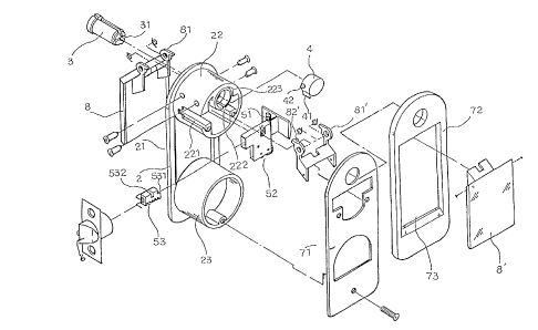
05 FIG. 1 is a perspective exploded view of a door lock
device of a preferred embodiment in accordance with the
present invention;
FIG. 2 is a perspective exploded view of a case
frame, a latch bolt device, a decoration plate, and a
pressing plate;
FIG. 3A is a schematic view illustrating an engage-
ment of a latch bolt device and a drive mechanism;
FIG. 3B is another schematic view illustrating an
engagement of a latch bolt device and a drive mechanism;
I5 FIG. 4A is a schematic view illustrating an appli-
cation of a door lock device while the door lock device
is locked;
FIG. 4B is a schematic view illustrating an appli
cation of a door lock device while the door lock device
is unlocked;
FIG. 5 is a schematic view illustrating an engage-
ment of a protruded block of a pressing device and an
elastic block of a lock fastener device;
FIG. 6A is a schematic view illustrating a first
pressing plate disposed on a case frame while the first
2

CA 02261511 1999-02-12
pressing plate is not operated;
FIG. 6B is a schematic view illustrating a drive
mechanism driving a latch bolt device to extend;
FIG. 7A is a schematic view illustrating a first
05 pressing plate disposed on a case frame while the first
press~.ng plate is operated;
FIG. 7B is a schematic view illustrating a drive
mechanism driving a latch bolt device to retract;
FIG. $ is a perspective exploded view of a door lock
device of another preferred embodiment in accordance with
the present invention; and
FIG. 9 is a schematic view illustrating an appli-
cation of a door lock device of another preferred embodi-
ment in accordance with the present invention.
Referring to FIGS. 1 to 7B, a door lock device is
disposed on a door 1. The door 1 has an upper through
hole 11 and a lower through hole 12. The door lock
device comprises a latch bolt device 6 disposed on the
door 1, a case frame 2 having an upper hollow cylinder 22
inserted through the upper through hole 11 and a lower
hollow cylinder 23 inserted through the lower through
hole 12, a first pressing plate 8 disposed on the
case frame 2, and a drive mechanism 5 disposed in the
upper holldw cylinder 22.
The case frame 2 further has a recess 21.
3

CA 02261511 1999-02-12
A core 3 has a driven block 31.
A lock fastener device 4 has a lateral elastic block
42 and a blocking bar 41.
The upper hollow cylinder 22 has an inner groove
05 222, a lateral slot 221, and a core seat 223 receiving
the core 3 and the lock fastener device 4. The core seat
223 has a bottom hole 224.
The drive mechanism 5 has a rack 53 to drive the
latch bolt device 6, and a drive frame 51 having a gear
set 52 to drive the rack 53. The rack 53 has an upper
groove 532 and an end groove 531. The rack 53 passes
through the lateral slot 221 to connect to the latch bolt
device 6. A pressing device 81' is disposed in the upper
hollow cylinder 22 to connect to the drive frame 51. The
pressing device 81' has a protruded block 82'.
The blocking bar 41 is inserted in the end groove 531.
A compression spring S is disposed between the drive frame
51 and the rack 53. A torsion spring S1 is disposed
between the core 3 and the lock fastener device 4.
The first pressing plate 8 has an upper pressing
portion 81. The recess 21 receives the first pressing
plate 8.
A locking plate 71 covers the upper through hole 11
and the lower through hole 12.
A decoration plate 72 is disposed on thd locking
4

CA 02261511 1999-02-12
plate 71. The decoration plate 72 has an opening 73. A
second pressing plate 8' is disposed on the decoration
plate 72. The opening 73 receives the second pressing
plate 8'. An upper portion of the second pressing plate 8'
05 is connected to the pressing device 81'.
The compression spring S pushes the latch bolt device
6 to extend (as shown in FIG. 3A). When the compression
spring S is compressed, the Latch bolt device 6 retracts
(as shown in FIG. 38).
20 Referring to FIG. 6B, the blocking bar 41 is inserted
in the end groove 531. The lateral elastic block 42 is
inserted in the bottom hole 224 (as shown in FIG. 4A).
Since the blocking bar 41 is inserted in the end groove
531, the latch bolt device 6 locks the door 1.
I5 When the second pressing plate 8' is operated, the
protruded block 82' contacts the lateral elastic block 42
to force the lateral elastic block 42 to retract (as
shown in FIG. 5). When the core 3 is rotated to contact
the lateral elastic block 42, the core 3 forces the
20 lateral elastic block 42 to retract.
When the lateral elastic block 42 disengages from
the bottom hole 224, the torsion spring S1 pushes the
lateral elastic block 42 to move (as shown in FIG. 4B).
Referring to FIGS. 8 and 9, a connection frame 92 is
25 disposed between the upper portion of the second pressing

CA 02261511 1999-02-12
plate 8' and the pressing device 81'. A link 91 has a
first end connected to the connection fraz~e 92 and
a second end connected to the second pressing plate 8'.
The user can press the second pressing plate 8' to
05 produce a pressing force P.
6

Dessin représentatif
Une figure unique qui représente un dessin illustrant l'invention.
États administratifs

Pour une meilleure compréhension de l'état de la demande ou brevet qui figure sur cette page, la rubrique Mise en garde , et les descriptions de Brevet , États administratifs , Taxes périodiques et Historique des paiements devraient être consultées.

États administratifs

Titre Date
Date de délivrance prévu 2003-06-03
(22) Dépôt 1999-02-12
Requête d'examen 1999-02-12
(41) Mise à la disponibilité du public 2000-08-12
(45) Délivré 2003-06-03
Réputé périmé 2010-02-12

Historique d'abandonnement

Il n'y a pas d'historique d'abandonnement

Historique des paiements

Type de taxes Anniversaire Échéance Montant payé Date payée
Requête d'examen 200,00 $ 1999-02-12
Le dépôt d'une demande de brevet 150,00 $ 1999-02-12
Taxe de maintien en état - Demande - nouvelle loi 2 2001-02-12 50,00 $ 2001-01-31
Taxe de maintien en état - Demande - nouvelle loi 3 2002-02-12 50,00 $ 2002-02-07
Taxe de maintien en état - Demande - nouvelle loi 4 2003-02-12 50,00 $ 2003-02-12
Taxe finale 150,00 $ 2003-03-21
Taxe de maintien en état - brevet - nouvelle loi 5 2004-02-12 100,00 $ 2004-02-10
Taxe de maintien en état - brevet - nouvelle loi 6 2005-02-14 100,00 $ 2004-12-22
Taxe de maintien en état - brevet - nouvelle loi 7 2006-02-13 100,00 $ 2006-01-25
Taxe de maintien en état - brevet - nouvelle loi 8 2007-02-12 100,00 $ 2007-02-06
Taxe de maintien en état - brevet - nouvelle loi 9 2008-02-12 100,00 $ 2008-02-12
Titulaires au dossier

Les titulaires actuels et antérieures au dossier sont affichés en ordre alphabétique.

Titulaires actuels au dossier
LIANG, CHIA PEL
Titulaires antérieures au dossier
S.O.
Les propriétaires antérieurs qui ne figurent pas dans la liste des « Propriétaires au dossier » apparaîtront dans d'autres documents au dossier.
Documents

Pour visionner les fichiers sélectionnés, entrer le code reCAPTCHA :


Pour visualiser une image, cliquer sur un lien dans la colonne description du document. Pour télécharger l'image (les images), cliquer l'une ou plusieurs cases à cocher dans la première colonne et ensuite cliquer sur le bouton "Télécharger sélection en format PDF (archive Zip)" ou le bouton "Télécharger sélection (en un fichier PDF fusionné)".

Liste des documents de brevet publiés et non publiés sur la BDBC .

Si vous avez des difficultés à accéder au contenu, veuillez communiquer avec le Centre de services à la clientèle au 1-866-997-1936, ou envoyer un courriel au Centre de service à la clientèle de l'OPIC.


Description du
Document 
Date
(yyyy-mm-dd) 
Nombre de pages   Taille de l'image (Ko) 
Dessins représentatifs 2000-08-09 1 16
Dessins représentatifs 2003-04-30 1 17
Page couverture 2003-04-30 1 46
Abrégé 1999-02-12 1 29
Description 1999-02-12 6 202
Revendications 1999-02-12 3 77
Dessins 1999-02-12 10 172
Dessins 1999-04-15 10 170
Page couverture 2000-08-09 1 43
Correspondance 2003-03-21 1 34
Taxes 2001-01-31 1 33
Cession 1999-02-12 3 83
Correspondance 1999-03-16 1 23
Correspondance 1999-04-15 6 129
Taxes 2008-02-12 1 42