Language selection

Search

Patent 2267150 Summary

Third-party information liability

Some of the information on this Web page has been provided by external sources. The Government of Canada is not responsible for the accuracy, reliability or currency of the information supplied by external sources. Users wishing to rely upon this information should consult directly with the source of the information. Content provided by external sources is not subject to official languages, privacy and accessibility requirements.

Claims and Abstract availability

Any discrepancies in the text and image of the Claims and Abstract are due to differing posting times. Text of the Claims and Abstract are posted:

  • At the time the application is open to public inspection;
  • At the time of issue of the patent (grant).
(12) Patent Application: (11) CA 2267150
(54) English Title: SYNGAS COMBUSTOR
(54) French Title: CHAMBRE DE COMBUSTION POUR GAZ DE SYNTHESE
Status: Dead
Bibliographic Data
(51) International Patent Classification (IPC):
  • F02B 43/10 (2006.01)
  • F23G 5/00 (2006.01)
  • F23G 5/027 (2006.01)
  • F23G 5/16 (2006.01)
  • F23G 5/46 (2006.01)
  • F23G 7/10 (2006.01)
(72) Inventors :
  • POGGEMOELLER, DAVID (Canada)
  • POGGEMOELLER, LARRY (Canada)
(73) Owners :
  • POGGEMOELLER, DAVID (Canada)
  • POGGEMOELLER, LARRY (Canada)
(71) Applicants :
  • POGGEMOELLER, DAVID (Canada)
  • POGGEMOELLER, LARRY (Canada)
(74) Agent:
(74) Associate agent:
(45) Issued:
(22) Filed Date: 1999-03-23
(41) Open to Public Inspection: 2000-09-23
Availability of licence: N/A
(25) Language of filing: English

Patent Cooperation Treaty (PCT): No

(30) Application Priority Data: None

Abstracts

English Abstract


Direct firing a turbine with syngas or biogas has received a lot of attention
since the oil shortages of the 1970's. Turbines are designed to run on high
BTU fuels
such as natural gas. Syngas is a low BTU fuel and previous attempts at using
this energy
for power generation on a small scale has been difficult. By designing a
specialized
combustion chamber for this low BTU gas ("syngas combustor"), we can create an
energy stream that will drive a gas turbine.
Traditional uses of Biomass Energy include the use of high-pressure steam.
This
greatly increases the operating costs of power generation for smaller
operations. The O2
starved Gasifier Primary combustion chamber produces a low BTU gas that is
high in
CO.


Claims

Note: Claims are shown in the official language in which they were submitted.
Sorry, the claims for patent document number 2267150 were not found.
Text is not available for all patent documents. The current dates of coverage are on the Currency of Information  page

Description

Note: Descriptions are shown in the official language in which they were submitted.


CA 02267150 1999-03-23
Fh~e
Gasifier/Turbine Power Option Using Syngas emissions from the Gasifier
Abstract: Direct firing a turbine with syngas or biogas has received a lot of
attention
since the oil shortages of the 1970's. Turbines are designed to run on high
BTU fuels
such as natural gas. Syngas is a low BTU fuel and previous attempts at using
this energy
for power generation on a small scale has been difficult. By designing a
specialized
combustion chamber for this low BTU gas ("syngas combustor"), we can create an
energy stream that will drive a gas turbine.
Traditional uses of Biomass Energy include the use of high-pressure steam.
This
greatly increases the operating costs of power generation for smaller
operations. The 02
starved Gasifier Primary combustion chamber produces a low BTU gas that is
high in
CO.
Specification:
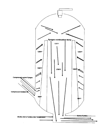
The process involves a Biomass Gasifier as an energy source, a gas cooling
system, compression system, and a gas/air heat transfer combustion chamber
(see
Diagram #3, "Syngas Combustor"), and a turbine/generation system.
The ECO Gasifier is a two-stage oxidation system with an oxygen starved
primary combustion chamber. Air velocities are kept very low and the biomass
fuel
remains in the chamber until oxidation is complete. Operational and
environmental test
results have proved the efficiency of the Eco Gasifier. The gases produced
from the
primary combustion chamber travel to a second chamber and are mixed with
enough air
to complete the oxidation process. The syngas produced in the primary and
mixed with
air will combust at 1200*f. Instead of adding the air to the syngas at this
point, we will
cool the syngas with a water spray and heat exchanger. The intent of this
process is to
drop out as much water as possible and cool the gas for the compression stage.
The cooled syngas is compressed to the requirements of the turbine. In the
model
(diagram 1) I have used 150psi. The compressed gas is mixed with compressed
air and
introduced into the syngas heat/combustion chamber.
The "syngas combustor" has two functions. One is to heat the ambient air and
syngas mixture to its' combustion temperature using the heat from the
combustion
process. The other is to combust the gas in the combustion chamber and allow
the gas
volume to pass to the turbine.
The program is designed for a specific turbine, but can be modified to fit
other
turbine designs. The combusted air stream passing to the turbine will be
967.63 lbs./min.
or 16.1 lbs./sec. at 1800*f.
The ECO Gasifier is a patented technology and the heat exchange technology is
already developed. The "syngas combustor" is the technology that we have
designed to
meet the energy requirements of the turbine. The syngas and air are introduced
from the
turbine compressor into an outer refractory lined chamber, which opens to the
combustion chamber or center portion of the "combustor". Some of the energy
from the
combustion in the chamber will transfer through the inner chamber wall to heat
the
incoming fuel mixture to its' combustion point. The temperature in the
combustion
chamber will change with fuel types. This process will be self sustaining but
will require
a heat source to start it. An igniter is needed in the top of the combustion
chamber for this


CA 02267150 1999-03-23
Dana
purpose. Dilution air is required to lower the temperature from the combustion
process to the required Turbine Inlet Temperature. The resulting air flow in
the
example given is 967.63 lbs/min. @1825.97*F.
Ken Davison

CA 02267150 1999-03-23
OXYGEN ENRICHMENT IN PRIMARY 2/4/99


FIRST PHASE COMBUSTION Engenaire
- Gas
turbines


SYNGAS TO GAS TURBINE


KEN J CUNNINGHAM 58


APR 98


WET FUEL BURNED GTPH 4 O.D. TONSIHr 2.4


FUEL SAMPLE WET WEIGHT 100 ASH PPH 7.2


DRY WEIGHT 60 FUEL SAMPLE % H20 40.00%


AMBIENT TEMPERATURE F. 68


RELATIVE HUMIDITY 60.00% LbsH20/LbAir 0.009118989


ALTITUDE Ft 1200 ATMOSPHERIC PSIA 14.09


OXYGEN SUPPLIED Lbs02/LbAir 0 PRIMARY SUPPLY GAS 02 % 22.94%
by Wt.


FUEL H2 CARRIED OVER 10% % by Vol.> H2 2.78%


H2 CARRYOVER TO CH4 10% CH4 0.15%


CO 31.09%


02 0.00%


C02 0.02%


BTUICuFt 101.8


FLUE GAS RE-INJECTION 0%


COMBUSTION AIR PREHEAT TEMP. 600.00 PRIMARY AIR MAKEUP Lbs/Min196.75
F.


%STOICHIOMETRIC PRIMARY AIR 40.00% PRIMARY C02 PRODUCTION 0.00
Lbs/Min


TRANSFER DUCT DIA. Ft 2 HOT PRIMARY ACFM 5513.62


GAS VELOCITY Ft/Sec 29.25


WATER INJECTION Lbs/Min 0


ITERATION BED OP. TEMP. F. 1652.11ACTUAL BED TEMP. F. 1652.11


WET GAS PROD. LbsIMin 322.29


BED DIAMETER Ft. 14 BED EXIT GAS VELOCITY FtlSec2.38


PRIMARY EXIT DUCT DIA Ft. 8 TRANSFER VELOCITY Ft/Sec 7.27


transfer duct length Ft. 16 RESIDENCE TIME Sec 2.20


PRIMARY GAS COOLDOWN


SPRAYDOWN TEMP. F. 250 WATER USAGE USGPM 13.83


PRIMARY GAS Lbs/Min 437.45


ACFM 10829.73


SPRAYDOWN CHAMBER EXIT Ft. 3 Ft/Sec 25.53


HEAT DUMP AIR SUPPLY ACFM 500000


ITERATION VENT AIR TEMP w VENT AIR DISCHARGE TEMP 92.38
F.


VENT DISCHARGE DUCT DIA Ft. 15 Ft/Sec 41.08


HEAT DUMP FLUE EXIT TEMP F. 80 WATER RECOVERY USGPM 24.94


EXIT Lbs/Min 229.80


EXIT ACFM 3496.27


FLUE EXIT DIA. Ft. 2 DUMP FLUE EXIT VEL.Ft/Sec 18.55


H2 0.21 02 0.00%
%


CH4 0.09% Ar 1.13%


H20 2.27% C02 0.04%


CO 32.23% S02 0.00%


N2 64.04% CALORIFIC VALUE BTU/CuFt 101.81


REMOTE MIXING ZONE
EXCESS TOTAL AIR 190.00% FD SUCTION FOR RMZ Lbs/Min 737.83
AIR DELIVERY ACFM 10295.98
RATIO CuFtAir/CuFtGas 2.94
MIXED GAS & AIR Lbs/Min 967.63

CA 02267150 1999-03-23
ACFM 13792~4~/gg


MIXED GAS AND AIR % by Weight


H2 0.05% 02 17.49%


CH4 0.02% Ar 1.27%


H20 1.23% C02 0.04%


CO 7.65% S02 0.00%


N2 72.24% CALORIFIC VALUE BTUICuFt 25.81


DMBUSTION CHAMBER ENTRY DIA 2 C.C. ENTRY VELOCITY. Ft/Sec73.17
Ft.


COMBUSTION TEMP. F. 1825.97


TOTAL AIR 110.00% 82.55
NAT
GAS
VALUE
AIR
MIXED
BTU/CuFt


WATER % 1.70%


CO % 0.00%


02% 10.45%


C02 % 14.92%


BTU/Min 464659


MMBTU/Hr 27.88


OVERALL GAS TURBINE THERMAL 30.00% KW 2451
EF


TONNES 02/DAY CONSUMPTION 0.00


OXYGEN COST, $/Tonne $ 35.00 0.0143


TOTAL OXYGEN COST $ - 0.0000


PRIMARY FAN


DELTA PRESSURE "H20 4.0


FAN EFFICIENCY 60% SUPPLIED H.P. 2.76


CA 02267150 1999-03-23
Symbol Legend
GTPH Green Tons Per Hour
O. D. Oven Dry
PPH Pounds Per Hour
IbsH2o/Ibsair Pounds of water per pound of air
OP. Operating
ACFM Actual Cubic Feet per Minute
FD Forced Draft
RMZ Remote Mixing Zone
MMBTU Million BTU
EF Efficiency

Representative Drawing
A single figure which represents the drawing illustrating the invention.
Administrative Status

For a clearer understanding of the status of the application/patent presented on this page, the site Disclaimer , as well as the definitions for Patent , Administrative Status , Maintenance Fee  and Payment History  should be consulted.

Administrative Status

Title Date
Forecasted Issue Date Unavailable
(22) Filed 1999-03-23
(41) Open to Public Inspection 2000-09-23
Dead Application 2001-10-18

Abandonment History

Abandonment Date Reason Reinstatement Date
2000-10-18 FAILURE TO COMPLETE
2001-03-23 FAILURE TO PAY APPLICATION MAINTENANCE FEE

Payment History

Fee Type Anniversary Year Due Date Amount Paid Paid Date
Application Fee $150.00 1999-03-23
Owners on Record

Note: Records showing the ownership history in alphabetical order.

Current Owners on Record
POGGEMOELLER, DAVID
POGGEMOELLER, LARRY
Past Owners on Record
None
Past Owners that do not appear in the "Owners on Record" listing will appear in other documentation within the application.
Documents

To view selected files, please enter reCAPTCHA code :


To view images, click a link in the Document Description column. To download the documents, select one or more checkboxes in the first column and then click the "Download Selected in PDF format (Zip Archive)" or the "Download Selected as Single PDF" button.

List of published and non-published patent-specific documents on the CPD .

If you have any difficulty accessing content, you can call the Client Service Centre at 1-866-997-1936 or send them an e-mail at CIPO Client Service Centre.


Document
Description 
Date
(yyyy-mm-dd) 
Number of pages   Size of Image (KB) 
Claims 2000-09-23 1 1
Abstract 1999-03-23 1 26
Description 1999-03-23 5 175
Drawings 1999-03-23 2 56
Cover Page 2000-09-18 1 36
Representative Drawing 2000-09-18 1 9
Assignment 1999-03-23 2 67
Correspondence 1999-05-07 1 28
Correspondence 1999-03-02 1 25
Correspondence 2000-07-18 1 2