Sélection de la langue

Search

Sommaire du brevet 2267150 

Énoncé de désistement de responsabilité concernant l'information provenant de tiers

Une partie des informations de ce site Web a été fournie par des sources externes. Le gouvernement du Canada n'assume aucune responsabilité concernant la précision, l'actualité ou la fiabilité des informations fournies par les sources externes. Les utilisateurs qui désirent employer cette information devraient consulter directement la source des informations. Le contenu fourni par les sources externes n'est pas assujetti aux exigences sur les langues officielles, la protection des renseignements personnels et l'accessibilité.

Disponibilité de l'Abrégé et des Revendications

L'apparition de différences dans le texte et l'image des Revendications et de l'Abrégé dépend du moment auquel le document est publié. Les textes des Revendications et de l'Abrégé sont affichés :

  • lorsque la demande peut être examinée par le public;
  • lorsque le brevet est émis (délivrance).
(12) Demande de brevet: (11) CA 2267150
(54) Titre français: CHAMBRE DE COMBUSTION POUR GAZ DE SYNTHESE
(54) Titre anglais: SYNGAS COMBUSTOR
Statut: Morte
Données bibliographiques
(51) Classification internationale des brevets (CIB):
  • F02B 43/10 (2006.01)
  • F23G 5/00 (2006.01)
  • F23G 5/027 (2006.01)
  • F23G 5/16 (2006.01)
  • F23G 5/46 (2006.01)
  • F23G 7/10 (2006.01)
(72) Inventeurs :
  • POGGEMOELLER, DAVID (Canada)
  • POGGEMOELLER, LARRY (Canada)
(73) Titulaires :
  • POGGEMOELLER, DAVID (Canada)
  • POGGEMOELLER, LARRY (Canada)
(71) Demandeurs :
  • POGGEMOELLER, DAVID (Canada)
  • POGGEMOELLER, LARRY (Canada)
(74) Agent:
(74) Co-agent:
(45) Délivré:
(22) Date de dépôt: 1999-03-23
(41) Mise à la disponibilité du public: 2000-09-23
Licence disponible: S.O.
(25) Langue des documents déposés: Anglais

Traité de coopération en matière de brevets (PCT): Non

(30) Données de priorité de la demande: S.O.

Abrégés

Abrégé anglais


Direct firing a turbine with syngas or biogas has received a lot of attention
since the oil shortages of the 1970's. Turbines are designed to run on high
BTU fuels
such as natural gas. Syngas is a low BTU fuel and previous attempts at using
this energy
for power generation on a small scale has been difficult. By designing a
specialized
combustion chamber for this low BTU gas ("syngas combustor"), we can create an
energy stream that will drive a gas turbine.
Traditional uses of Biomass Energy include the use of high-pressure steam.
This
greatly increases the operating costs of power generation for smaller
operations. The O2
starved Gasifier Primary combustion chamber produces a low BTU gas that is
high in
CO.

Revendications

Note : Les revendications sont présentées dans la langue officielle dans laquelle elles ont été soumises.

Désolé, les revendications concernant le document de brevet no 2267150 sont introuvables.
Les textes ne sont pas disponibles pour tous les documents de brevet. L'étendue des dates couvertes est disponible sur la section Actualité de l'information .

Description

Note : Les descriptions sont présentées dans la langue officielle dans laquelle elles ont été soumises.


CA 02267150 1999-03-23
Fh~e
Gasifier/Turbine Power Option Using Syngas emissions from the Gasifier
Abstract: Direct firing a turbine with syngas or biogas has received a lot of
attention
since the oil shortages of the 1970's. Turbines are designed to run on high
BTU fuels
such as natural gas. Syngas is a low BTU fuel and previous attempts at using
this energy
for power generation on a small scale has been difficult. By designing a
specialized
combustion chamber for this low BTU gas ("syngas combustor"), we can create an
energy stream that will drive a gas turbine.
Traditional uses of Biomass Energy include the use of high-pressure steam.
This
greatly increases the operating costs of power generation for smaller
operations. The 02
starved Gasifier Primary combustion chamber produces a low BTU gas that is
high in
CO.
Specification:
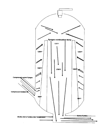
The process involves a Biomass Gasifier as an energy source, a gas cooling
system, compression system, and a gas/air heat transfer combustion chamber
(see
Diagram #3, "Syngas Combustor"), and a turbine/generation system.
The ECO Gasifier is a two-stage oxidation system with an oxygen starved
primary combustion chamber. Air velocities are kept very low and the biomass
fuel
remains in the chamber until oxidation is complete. Operational and
environmental test
results have proved the efficiency of the Eco Gasifier. The gases produced
from the
primary combustion chamber travel to a second chamber and are mixed with
enough air
to complete the oxidation process. The syngas produced in the primary and
mixed with
air will combust at 1200*f. Instead of adding the air to the syngas at this
point, we will
cool the syngas with a water spray and heat exchanger. The intent of this
process is to
drop out as much water as possible and cool the gas for the compression stage.
The cooled syngas is compressed to the requirements of the turbine. In the
model
(diagram 1) I have used 150psi. The compressed gas is mixed with compressed
air and
introduced into the syngas heat/combustion chamber.
The "syngas combustor" has two functions. One is to heat the ambient air and
syngas mixture to its' combustion temperature using the heat from the
combustion
process. The other is to combust the gas in the combustion chamber and allow
the gas
volume to pass to the turbine.
The program is designed for a specific turbine, but can be modified to fit
other
turbine designs. The combusted air stream passing to the turbine will be
967.63 lbs./min.
or 16.1 lbs./sec. at 1800*f.
The ECO Gasifier is a patented technology and the heat exchange technology is
already developed. The "syngas combustor" is the technology that we have
designed to
meet the energy requirements of the turbine. The syngas and air are introduced
from the
turbine compressor into an outer refractory lined chamber, which opens to the
combustion chamber or center portion of the "combustor". Some of the energy
from the
combustion in the chamber will transfer through the inner chamber wall to heat
the
incoming fuel mixture to its' combustion point. The temperature in the
combustion
chamber will change with fuel types. This process will be self sustaining but
will require
a heat source to start it. An igniter is needed in the top of the combustion
chamber for this


CA 02267150 1999-03-23
Dana
purpose. Dilution air is required to lower the temperature from the combustion
process to the required Turbine Inlet Temperature. The resulting air flow in
the
example given is 967.63 lbs/min. @1825.97*F.
Ken Davison

CA 02267150 1999-03-23
OXYGEN ENRICHMENT IN PRIMARY 2/4/99


FIRST PHASE COMBUSTION Engenaire
- Gas
turbines


SYNGAS TO GAS TURBINE


KEN J CUNNINGHAM 58


APR 98


WET FUEL BURNED GTPH 4 O.D. TONSIHr 2.4


FUEL SAMPLE WET WEIGHT 100 ASH PPH 7.2


DRY WEIGHT 60 FUEL SAMPLE % H20 40.00%


AMBIENT TEMPERATURE F. 68


RELATIVE HUMIDITY 60.00% LbsH20/LbAir 0.009118989


ALTITUDE Ft 1200 ATMOSPHERIC PSIA 14.09


OXYGEN SUPPLIED Lbs02/LbAir 0 PRIMARY SUPPLY GAS 02 % 22.94%
by Wt.


FUEL H2 CARRIED OVER 10% % by Vol.> H2 2.78%


H2 CARRYOVER TO CH4 10% CH4 0.15%


CO 31.09%


02 0.00%


C02 0.02%


BTUICuFt 101.8


FLUE GAS RE-INJECTION 0%


COMBUSTION AIR PREHEAT TEMP. 600.00 PRIMARY AIR MAKEUP Lbs/Min196.75
F.


%STOICHIOMETRIC PRIMARY AIR 40.00% PRIMARY C02 PRODUCTION 0.00
Lbs/Min


TRANSFER DUCT DIA. Ft 2 HOT PRIMARY ACFM 5513.62


GAS VELOCITY Ft/Sec 29.25


WATER INJECTION Lbs/Min 0


ITERATION BED OP. TEMP. F. 1652.11ACTUAL BED TEMP. F. 1652.11


WET GAS PROD. LbsIMin 322.29


BED DIAMETER Ft. 14 BED EXIT GAS VELOCITY FtlSec2.38


PRIMARY EXIT DUCT DIA Ft. 8 TRANSFER VELOCITY Ft/Sec 7.27


transfer duct length Ft. 16 RESIDENCE TIME Sec 2.20


PRIMARY GAS COOLDOWN


SPRAYDOWN TEMP. F. 250 WATER USAGE USGPM 13.83


PRIMARY GAS Lbs/Min 437.45


ACFM 10829.73


SPRAYDOWN CHAMBER EXIT Ft. 3 Ft/Sec 25.53


HEAT DUMP AIR SUPPLY ACFM 500000


ITERATION VENT AIR TEMP w VENT AIR DISCHARGE TEMP 92.38
F.


VENT DISCHARGE DUCT DIA Ft. 15 Ft/Sec 41.08


HEAT DUMP FLUE EXIT TEMP F. 80 WATER RECOVERY USGPM 24.94


EXIT Lbs/Min 229.80


EXIT ACFM 3496.27


FLUE EXIT DIA. Ft. 2 DUMP FLUE EXIT VEL.Ft/Sec 18.55


H2 0.21 02 0.00%
%


CH4 0.09% Ar 1.13%


H20 2.27% C02 0.04%


CO 32.23% S02 0.00%


N2 64.04% CALORIFIC VALUE BTU/CuFt 101.81


REMOTE MIXING ZONE
EXCESS TOTAL AIR 190.00% FD SUCTION FOR RMZ Lbs/Min 737.83
AIR DELIVERY ACFM 10295.98
RATIO CuFtAir/CuFtGas 2.94
MIXED GAS & AIR Lbs/Min 967.63

CA 02267150 1999-03-23
ACFM 13792~4~/gg


MIXED GAS AND AIR % by Weight


H2 0.05% 02 17.49%


CH4 0.02% Ar 1.27%


H20 1.23% C02 0.04%


CO 7.65% S02 0.00%


N2 72.24% CALORIFIC VALUE BTUICuFt 25.81


DMBUSTION CHAMBER ENTRY DIA 2 C.C. ENTRY VELOCITY. Ft/Sec73.17
Ft.


COMBUSTION TEMP. F. 1825.97


TOTAL AIR 110.00% 82.55
NAT
GAS
VALUE
AIR
MIXED
BTU/CuFt


WATER % 1.70%


CO % 0.00%


02% 10.45%


C02 % 14.92%


BTU/Min 464659


MMBTU/Hr 27.88


OVERALL GAS TURBINE THERMAL 30.00% KW 2451
EF


TONNES 02/DAY CONSUMPTION 0.00


OXYGEN COST, $/Tonne $ 35.00 0.0143


TOTAL OXYGEN COST $ - 0.0000


PRIMARY FAN


DELTA PRESSURE "H20 4.0


FAN EFFICIENCY 60% SUPPLIED H.P. 2.76


CA 02267150 1999-03-23
Symbol Legend
GTPH Green Tons Per Hour
O. D. Oven Dry
PPH Pounds Per Hour
IbsH2o/Ibsair Pounds of water per pound of air
OP. Operating
ACFM Actual Cubic Feet per Minute
FD Forced Draft
RMZ Remote Mixing Zone
MMBTU Million BTU
EF Efficiency

Dessin représentatif
Une figure unique qui représente un dessin illustrant l'invention.
États administratifs

Pour une meilleure compréhension de l'état de la demande ou brevet qui figure sur cette page, la rubrique Mise en garde , et les descriptions de Brevet , États administratifs , Taxes périodiques et Historique des paiements devraient être consultées.

États administratifs

Titre Date
Date de délivrance prévu Non disponible
(22) Dépôt 1999-03-23
(41) Mise à la disponibilité du public 2000-09-23
Demande morte 2001-10-18

Historique d'abandonnement

Date d'abandonnement Raison Reinstatement Date
2000-10-18 Inachevé
2001-03-23 Taxe périodique sur la demande impayée

Historique des paiements

Type de taxes Anniversaire Échéance Montant payé Date payée
Le dépôt d'une demande de brevet 150,00 $ 1999-03-23
Titulaires au dossier

Les titulaires actuels et antérieures au dossier sont affichés en ordre alphabétique.

Titulaires actuels au dossier
POGGEMOELLER, DAVID
POGGEMOELLER, LARRY
Titulaires antérieures au dossier
S.O.
Les propriétaires antérieurs qui ne figurent pas dans la liste des « Propriétaires au dossier » apparaîtront dans d'autres documents au dossier.
Documents

Pour visionner les fichiers sélectionnés, entrer le code reCAPTCHA :


Pour visualiser une image, cliquer sur un lien dans la colonne description du document. Pour télécharger l'image (les images), cliquer l'une ou plusieurs cases à cocher dans la première colonne et ensuite cliquer sur le bouton "Télécharger sélection en format PDF (archive Zip)" ou le bouton "Télécharger sélection (en un fichier PDF fusionné)".

Liste des documents de brevet publiés et non publiés sur la BDBC .

Si vous avez des difficultés à accéder au contenu, veuillez communiquer avec le Centre de services à la clientèle au 1-866-997-1936, ou envoyer un courriel au Centre de service à la clientèle de l'OPIC.


Description du
Document 
Date
(yyyy-mm-dd) 
Nombre de pages   Taille de l'image (Ko) 
Revendications 2000-09-23 1 1
Abrégé 1999-03-23 1 26
Description 1999-03-23 5 175
Dessins 1999-03-23 2 56
Page couverture 2000-09-18 1 36
Dessins représentatifs 2000-09-18 1 9
Cession 1999-03-23 2 67
Correspondance 1999-05-07 1 28
Correspondance 1999-03-02 1 25
Correspondance 2000-07-18 1 2