Language selection

Search

Patent 2274239 Summary

Third-party information liability

Some of the information on this Web page has been provided by external sources. The Government of Canada is not responsible for the accuracy, reliability or currency of the information supplied by external sources. Users wishing to rely upon this information should consult directly with the source of the information. Content provided by external sources is not subject to official languages, privacy and accessibility requirements.

Claims and Abstract availability

Any discrepancies in the text and image of the Claims and Abstract are due to differing posting times. Text of the Claims and Abstract are posted:

  • At the time the application is open to public inspection;
  • At the time of issue of the patent (grant).
(12) Patent: (11) CA 2274239
(54) English Title: CONCRETE MASONRY REINFORCEMENT
(54) French Title: CHAINAGE DE MACONNERIE DE BETON
Status: Expired
Bibliographic Data
(51) International Patent Classification (IPC):
  • E04C 5/01 (2006.01)
  • E04B 2/20 (2006.01)
  • E04B 2/24 (2006.01)
  • E04C 5/02 (2006.01)
(72) Inventors :
  • HATZINKOLAS, MICHAEL (Canada)
(73) Owners :
  • LATHICO INDUSTRIES LTD. (Canada)
(71) Applicants :
  • HATZINKOLAS, MICHAEL (Canada)
(74) Agent: BERESKIN & PARR LLP/S.E.N.C.R.L.,S.R.L.
(74) Associate agent:
(45) Issued: 2006-03-14
(22) Filed Date: 1999-06-10
(41) Open to Public Inspection: 2000-12-10
Examination requested: 2003-06-04
Availability of licence: N/A
(25) Language of filing: English

Patent Cooperation Treaty (PCT): No

(30) Application Priority Data: None

Abstracts

English Abstract

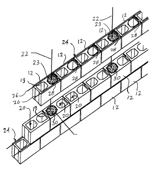
In a partially grouted concrete masonry wall, the bed joint reinforcement is provided by a set of rings spaced along the mortar between two adjacent courses of blocks and wire strands on opposite sides of the rings. Each of the grouted cells of the wall is surrounded by reinforcing rings embedded in the mortar. The rings support the columns of grouting in the wall and more effectively transfer loads to the bed joint reinforcement than does conventional truss or ladder style bed joint reinforcement. Between courses where bed joint reinforcement is not used, independent rings may be employed to support the grouting columns.


French Abstract

Dans un mur de maçonnerie en béton partiellement cimenté, l'armature des joints d'assise est constituée d'un ensemble d'anneaux espacés le long du mortier entre deux rangées adjacentes de blocs et de fils d'acier de chaque côté des anneaux. Chacune des alvéoles cimentées du mur est encerclée par des anneaux de renforcement noyés dans le mortier. Les anneaux soutiennent les colonnes de cimentation dans le mur et transfèrent les charges vers l'armature des joints d'assise de manière plus efficace que ne le fait l'armature de joint d'assise conventionnelle de type treillis ou échelle. Dans les parties intermédiaires où aucune armature de joint d'assise n'est utilisée, des anneaux indépendants peuvent être employés pour soutenir les colonnes de cimentation.

Claims

Note: Claims are shown in the official language in which they were submitted.


-5-

Claims:

1. A joint reinforcement for use in a concrete block wall, the concrete block
wall including a plurality of blocks arranged in plural courses, the blocks
having hollow cores that align in upright cells through the courses at
intervals
along the wall, mortar joining adjacent blocks, and grouting filling selected
ones of the cells, said reinforcement comprising:
a plurality of reinforcing strands along each of the selected cells,
wherein the strands are unembedded in the grouting; and
a plurality of reinforcing rings connected to the reinforcing strands,
each reinforcing ring surrounding the grouting in a respective one of the
selected cells between two adjacent courses.

2. A reinforcement according to Claim 1 wherein the rings are steel
reinforcing
rings.

3. A reinforcement according to Claim 2 including pairs of reinforcing strands
extending along the wall between adjacent courses, the strands being
embedded in the mortar on opposite sides of the hollow cores.

4. A reinforcement according to Claim 3 wherein the reinforcing strands are
wire strands.

5. A reinforcement according to Claim 3, 4 or 5 wherein the reinforcing
strands have an oblong profile.

6. A reinforcement according to any one of Claims 2 through 5 wherein the
reinforcing rings are round wire.


Description

Note: Descriptions are shown in the official language in which they were submitted.


CA 02274239 1999-06-10
CONCRETE MASONRY REINFORCEMENT
FIELD OF THE INVENTION
The present invention relates to the reinforcement of partially grouted
concrete masonry walls.
BACKGROUND
Partially grouted concrete masonry walls of the type in question
conventionally have two types of reinforcement. Vertical reinforcement in the
form of
rebar is used in the grouted cells of the wall. Horizontal reinforcement is
provided by
bed joint reinforcement, typically in a "ladder" or "truss" configuration. In
such
structures, the full capacity of the reinforcement is not utilized because of
the
mismatch between the elastic modulus of the steel of the reinforcement and
that of
the mortar used in fabricating the wall. In addition, the difference between
the
Poisson's ratios of the steel and the concrete grout causes the concrete to
split
prematurely.
The present invention aims at the provision of mechanisms to improve
utilization of the reinforcement.
SUMMARY
According to one aspect of the present invention there is provided a
reinforcement for use in a concrete block wall comprising:
a plurality of blocks arranged in plural courses, the blocks having hollow
cores that align in upright cells through the courses at intervals along the
wall;
mortar joining adjacent blocks;
grouting filling selected ones of the cells; and
reinforcing strands along each of the selected cells,
said reinforcement comprising a plurality of reinforcing rings each
surrounding the
grouting in a respective one of the selected cells between two adjacent
courses.

CA 02274239 1999-06-10
_2_
The rings support the column of grouting where it passes through the
mortar joint between the blocks, thus mitigating the differences in properties
between
the reinforced cell grouting, the mortar and the reinforcement.
According to another aspect of the present invention there is provided
bed joint reinforcement for a concrete masonry wall that is at least partially
grouted,
said reinforcement comprising:
a pair of spaced apart, substantially parallel side strands; and
a plurality of rings joining the side strands, substantially parallel to the
side strands.
When the reinforcement is installed, the rings surround the grouted
cells in the wall and transfer loads directly from the grouting columns to the
side
strands to reinforce the wall horizontally and reduce stress concentrations.
At the
same time, the rings support the columns of grout as discussed above.
The invention also provides, according to other aspects thereof, walls
incorporating the reinforcing rings and the bed joint reinforcement.
The rings may be of any suitable shape, for example circular, square or
other polygon. They are preferably formed from round steel wire. The side
stands
are preferably steel wire, flattened to present an oblong profile with a
height
approximately equal to that of the rings. It is preferred that the rings are
co-planar
with the side strands and welded tangentially to them. The rings may also be
lapped
and welded, but this increases the thickness of the reinforcement.
BRIEF DESCRIPTION OF THE DRAWINGS
In the accompanying drawings, which illustrate exemplary embodiments
of the present invention:
Figure 1 is an elevation of a masonry wall;
Figure 2 is a plan view of a bed joint reinforcement;

CA 02274239 1999-06-10
-3-
Figure 3 is a cross section on line 3 - 3 of Figure 2;
Figure 4 is a view along line 4 - 4 of Figure 1; and
Figure 5 is an exploded isometric of the wall.
DETAILED DESCRIPTION
Referring to the accompanying drawings, Figure 1 illustrates a wall 10
composed of masonry blocks 12 arranged in superimposed courses 14. The joints
between adjacent courses and between adjacent blocks in the same course are
formed with mortar 18. The blocks are hollow core blocks with two cavities 19
(Figures 4 and 5) per block. The cavities align through the courses to provide
vertical cells 20 through the wall. At intervals along the wall, the cells
have vertical
steel reinforcing rods 22 extending along their centers. The rods are embedded
in
grout 23 (Figures 4 and 5). The grout forms, with the vertical reinforcing
rods,
vertical columns in the wall's structure.
The wall is also reinforced horizontally with bed joint reinforcement
between selected adjacent courses of the blocks. As illustrated in Figures 2
through
5, the bed joint reinforcement 24 includes two parallel side rods 26. These
are steel
rods flattened in their vertical dimension to present an oval profile. The
rods are
joined by cross links, which are rings 28 that align with cells 20 in the
wall. As
illustrated in Figures 4 and 5, rings are provided to align with alternate
cells along the
wall, although in the illustrated wall, only every sixth cell is grouted.
As shown in the exploded view of Figure 5, the bed joint reinforcement
24 is used in alternate joints. In the intervening joints rings 30 are
embedded in the
mortar around the grouted cells to confine the grout 23.
With this structure, the rings 28 and 30 confine the grouted cells where
they pass through the mortar to support the columns. The rings that are
incorporated
into the bed joint reinforcement transfer loads between the cells and the
steel side

CA 02274239 1999-06-10
-4-
rods 26 to provide a more effective use of the strength of the side rods 26
than would
be the case if the loads were to be transferred to the side rods through the
mortar.
While particular embodiments of the invention has been described in
the foregoing, it is to be understood that other embodiments are possible
within the
scope of the invention and are intended to be included herein. Thus, for
example,
the rings of the illustrated embodiment are circular in shape but other shapes
may be
employed, including various polygons. The rings are shown parallel to and co-
planar
with the side rods and welded to them at the points of contact. In other
embodiments,
the rings may overlap the side rods, although this is not a preferred
construction. At
those locations where there is no vertical reinforcement, the rings may be
omitted,
and the side rods connected by straight bars. The invention is therefore to be
considered limited solely by the scope of the appended claims.

Representative Drawing
A single figure which represents the drawing illustrating the invention.
Administrative Status

For a clearer understanding of the status of the application/patent presented on this page, the site Disclaimer , as well as the definitions for Patent , Administrative Status , Maintenance Fee  and Payment History  should be consulted.

Administrative Status

Title Date
Forecasted Issue Date 2006-03-14
(22) Filed 1999-06-10
(41) Open to Public Inspection 2000-12-10
Examination Requested 2003-06-04
(45) Issued 2006-03-14
Expired 2019-06-10

Abandonment History

There is no abandonment history.

Payment History

Fee Type Anniversary Year Due Date Amount Paid Paid Date
Application Fee $150.00 1999-06-10
Registration of a document - section 124 $100.00 1999-09-22
Maintenance Fee - Application - New Act 2 2001-06-11 $50.00 2001-06-08
Maintenance Fee - Application - New Act 3 2002-06-10 $50.00 2002-06-13
Request for Examination $400.00 2003-06-04
Maintenance Fee - Application - New Act 4 2003-06-10 $100.00 2003-06-04
Maintenance Fee - Application - New Act 5 2004-06-10 $200.00 2004-04-23
Maintenance Fee - Application - New Act 6 2005-06-10 $200.00 2005-05-12
Final Fee $300.00 2005-12-21
Maintenance Fee - Patent - New Act 7 2006-06-12 $200.00 2006-05-03
Maintenance Fee - Patent - New Act 8 2007-06-11 $100.00 2007-01-18
Maintenance Fee - Patent - New Act 9 2008-06-10 $100.00 2007-12-06
Maintenance Fee - Patent - New Act 10 2009-06-10 $125.00 2009-03-24
Maintenance Fee - Patent - New Act 11 2010-06-10 $125.00 2010-03-09
Maintenance Fee - Patent - New Act 12 2011-06-10 $325.00 2011-06-28
Maintenance Fee - Patent - New Act 13 2012-06-11 $125.00 2012-05-17
Maintenance Fee - Patent - New Act 14 2013-06-10 $125.00 2013-03-11
Maintenance Fee - Patent - New Act 15 2014-06-10 $225.00 2014-03-10
Maintenance Fee - Patent - New Act 16 2015-06-10 $225.00 2014-11-24
Maintenance Fee - Patent - New Act 17 2016-06-10 $225.00 2016-01-15
Maintenance Fee - Patent - New Act 18 2017-06-12 $225.00 2017-02-27
Maintenance Fee - Patent - New Act 19 2018-06-11 $225.00 2018-03-05
Owners on Record

Note: Records showing the ownership history in alphabetical order.

Current Owners on Record
LATHICO INDUSTRIES LTD.
Past Owners on Record
HATZINKOLAS, MICHAEL
Past Owners that do not appear in the "Owners on Record" listing will appear in other documentation within the application.
Documents

To view selected files, please enter reCAPTCHA code :


To view images, click a link in the Document Description column. To download the documents, select one or more checkboxes in the first column and then click the "Download Selected in PDF format (Zip Archive)" or the "Download Selected as Single PDF" button.

List of published and non-published patent-specific documents on the CPD .

If you have any difficulty accessing content, you can call the Client Service Centre at 1-866-997-1936 or send them an e-mail at CIPO Client Service Centre.


Document
Description 
Date
(yyyy-mm-dd) 
Number of pages   Size of Image (KB) 
Abstract 1999-06-10 1 17
Representative Drawing 2006-02-10 1 16
Description 1999-06-10 4 152
Cover Page 2006-02-10 1 42
Claims 1999-06-10 1 30
Representative Drawing 2000-12-04 1 17
Drawings 1999-06-10 2 56
Drawings 1999-09-22 2 58
Cover Page 2000-12-04 1 41
Claims 2005-08-30 1 30
Assignment 1999-06-10 2 78
Correspondence 1999-07-20 1 33
Correspondence 1999-08-23 2 76
Correspondence 1999-09-21 1 2
Assignment 1999-09-22 2 60
Correspondence 1999-09-22 3 93
Assignment 1999-06-10 4 154
Assignment 1999-12-17 3 92
Correspondence 2001-06-19 1 13
Correspondence 2001-06-19 1 16
Correspondence 2002-07-19 1 23
Correspondence 2003-03-06 2 71
Correspondence 2003-04-01 1 12
Correspondence 2003-05-15 2 68
Correspondence 2003-06-03 1 16
Correspondence 2003-06-03 1 17
Fees 2003-06-04 1 32
Prosecution-Amendment 2003-06-04 1 33
Prosecution-Amendment 2005-06-28 2 59
Fees 2004-04-23 1 34
Fees 2005-05-12 1 27
Prosecution-Amendment 2005-08-30 3 114
Correspondence 2005-12-21 1 35
Fees 2006-05-03 1 39
Correspondence 2007-01-18 1 40
Fees 2007-01-18 1 23
Correspondence 2007-02-20 1 27
Correspondence 2007-02-12 2 58
Fees 2007-12-06 1 24
Fees 2011-06-28 1 47
Fees 2012-05-17 1 74
Fees 2013-03-11 1 140
Fees 2014-03-10 1 131