Some of the information on this Web page has been provided by external sources. The Government of Canada is not responsible for the accuracy, reliability or currency of the information supplied by external sources. Users wishing to rely upon this information should consult directly with the source of the information. Content provided by external sources is not subject to official languages, privacy and accessibility requirements.
Any discrepancies in the text and image of the Claims and Abstract are due to differing posting times. Text of the Claims and Abstract are posted:
| (12) Patent: | (11) CA 2277653 |
|---|---|
| (54) English Title: | CYLINDRICAL HOLOGRAPHIC DISPLAY DEVICE |
| (54) French Title: | DISPOSITIF D'AFFICHAGE HOLOGRAPHIQUE CYLINDRIQUE |
| Status: | Deemed expired |
| (51) International Patent Classification (IPC): |
|
|---|---|
| (72) Inventors : |
|
| (73) Owners : |
|
| (71) Applicants : |
|
| (74) Agent: | |
| (74) Associate agent: | |
| (45) Issued: | 2005-01-11 |
| (22) Filed Date: | 1999-07-20 |
| (41) Open to Public Inspection: | 2001-01-20 |
| Examination requested: | 2003-05-05 |
| Availability of licence: | Yes |
| (25) Language of filing: | English |
| Patent Cooperation Treaty (PCT): | No |
|---|
| (30) Application Priority Data: | None |
|---|
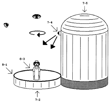
A holographic display device for displaying a 3-dimensional
image has a cylindrical casing and a horizontally-placed circular
reflection-type hologram in order to project an upright
orthoscopic real image having both horizontal and vertical
parallaxes. The hologram may be illuminated by a point source of
white light, preferably a high-efficiency light emitting diode,
securely attached to telescopic or flexible means integrated into
the holographic display device. The hologram may be rotated by an
electric motor in order to display all sides of the holographic
image. The means for mounting the point source of white light may
have the same diameter as the cylindrical casing in order to
slidably house the cylindrical casing. This invention relates to
holographic display devices for displaying a 3-dimensional image,
and the principal use of the invention is for optical decoration.
Note: Claims are shown in the official language in which they were submitted.
Note: Descriptions are shown in the official language in which they were submitted.
For a clearer understanding of the status of the application/patent presented on this page, the site Disclaimer , as well as the definitions for Patent , Administrative Status , Maintenance Fee and Payment History should be consulted.
| Title | Date |
|---|---|
| Forecasted Issue Date | 2005-01-11 |
| (22) Filed | 1999-07-20 |
| (41) Open to Public Inspection | 2001-01-20 |
| Examination Requested | 2003-05-05 |
| (45) Issued | 2005-01-11 |
| Deemed Expired | 2007-07-20 |
There is no abandonment history.
| Fee Type | Anniversary Year | Due Date | Amount Paid | Paid Date |
|---|---|---|---|---|
| Application Fee | $150.00 | 1999-07-20 | ||
| Maintenance Fee - Application - New Act | 2 | 2001-07-20 | $50.00 | 2001-05-07 |
| Maintenance Fee - Application - New Act | 3 | 2002-07-22 | $50.00 | 2002-05-07 |
| Request for Examination | $200.00 | 2003-05-05 | ||
| Maintenance Fee - Application - New Act | 4 | 2003-07-21 | $50.00 | 2003-05-05 |
| Maintenance Fee - Application - New Act | 5 | 2004-07-20 | $75.00 | 2003-12-23 |
| Maintenance Fee - Application - New Act | 6 | 2005-07-20 | $75.00 | 2003-12-23 |
| Final Fee | $150.00 | 2004-11-04 |
Note: Records showing the ownership history in alphabetical order.
| Current Owners on Record |
|---|
| SUNATORI, GO SIMON |
| Past Owners on Record |
|---|
| None |

