Sélection de la langue

Search

Sommaire du brevet 2277653 

Énoncé de désistement de responsabilité concernant l'information provenant de tiers

Une partie des informations de ce site Web a été fournie par des sources externes. Le gouvernement du Canada n'assume aucune responsabilité concernant la précision, l'actualité ou la fiabilité des informations fournies par les sources externes. Les utilisateurs qui désirent employer cette information devraient consulter directement la source des informations. Le contenu fourni par les sources externes n'est pas assujetti aux exigences sur les langues officielles, la protection des renseignements personnels et l'accessibilité.

Disponibilité de l'Abrégé et des Revendications

L'apparition de différences dans le texte et l'image des Revendications et de l'Abrégé dépend du moment auquel le document est publié. Les textes des Revendications et de l'Abrégé sont affichés :

  • lorsque la demande peut être examinée par le public;
  • lorsque le brevet est émis (délivrance).
(12) Brevet: (11) CA 2277653
(54) Titre français: DISPOSITIF D'AFFICHAGE HOLOGRAPHIQUE CYLINDRIQUE
(54) Titre anglais: CYLINDRICAL HOLOGRAPHIC DISPLAY DEVICE
Statut: Réputé périmé
Données bibliographiques
Abrégés

Abrégé anglais


A holographic display device for displaying a 3-dimensional
image has a cylindrical casing and a horizontally-placed circular
reflection-type hologram in order to project an upright
orthoscopic real image having both horizontal and vertical
parallaxes. The hologram may be illuminated by a point source of
white light, preferably a high-efficiency light emitting diode,
securely attached to telescopic or flexible means integrated into
the holographic display device. The hologram may be rotated by an
electric motor in order to display all sides of the holographic
image. The means for mounting the point source of white light may
have the same diameter as the cylindrical casing in order to
slidably house the cylindrical casing. This invention relates to
holographic display devices for displaying a 3-dimensional image,
and the principal use of the invention is for optical decoration.

Revendications

Note : Les revendications sont présentées dans la langue officielle dans laquelle elles ont été soumises.


Claims

The embodiments of the invention in which an exclusive
property or privilege is claimed are defined as follows:
1. A holographic display device for displaying a 3-dimensional
image, comprising:
a singularity of horizontally-placed circular reflection-type
hologram having a top surface;
a circular mount for supporting the hologram;
a cylindrical casing far supporting the circular mount;
a point source of white light for illuminating the hologram;
means for mounting the point source of white light; and
a power supply and a control circuit, securely attached to
the cylindrical casing, and operably connected to the point source
of white light;
the horizontally-placed circular reflection-type hologram having
both horizontal and vertical parallaxes, the horizontally-placed
circular reflection-type hologram projecting an orthoscopic real
image perpendicularly from the top surface of the hologram when
illuminated by the point source of white light directly from
above.
2. The holographic display device for displaying a 3-dimensional


-7-


image as defined in claim 1, in which the point source of white
light is a high-efficiency light emitting diode.
3. The holographic display device for displaying a 3-dimensional
image as defined in claim 1 or claim 2, in which the means for
mounting the point source of white light is telescopically or
flexibly extensible so that the angle- of incidence may be
adjusted.
4. The holographic display device for displaying a 3-dimensional
image as defined in claim 1 or claim 2, in which the means for
mounting the point source of white light is substantially
cylindrical and hallow, having the same diameter as the
cylindrical casing, and having the bottom portion defining a hole
to slidably house the cylindrical casing.
5. A holographic display device for displaying a 3-dimensional
image, comprising:
a singularity of horizontally-placed circular reflection-type
hologram having a top surface;
a circular mount for rotatably supporting the hologram,
having a plurality of legs at the bottom, conically converging to
one point;
a cylindrical casing for supporting the circular mount;
an electric motor for rotating the circular mount, securely
attached to the cylindrical casing; and


-8-


a power supply and a control circuit, securely attached to
the cylindrical casing, and operably connected to the electric
motor;
the horizontally-placed circular reflection-type hologram having
both horizontal and vertical parallaxes, the horizontally-placed
circular reflection-type hologram projecting an orthoscopic real
image perpendicularly from the top surface of the hologram when
illuminated by the point source of white light directly from
above.
6. The holographic display device for displaying a 3-dimensional
image as defined in claim 1 or claim 2 or claim 3 or claim 4 or
claim 5, in which the circular reflection-type hologram is
computer-generated, and has full colour.


-9-

Description

Note : Les descriptions sont présentées dans la langue officielle dans laquelle elles ont été soumises.


CA 02277653 1999-07-20
Description
Titl~
Cylindrical Holographic Display Device
Technical Field
This invention relates to holographic display devices for
displaying a 3-dimensional image, more particularly to a
cylindrical holographic display device.
Background Art
There are many instances where it would be desirable to be
able to have a compact holographic display devices for displaying
a 3-dimensional image such as a statue.
A large number of patents disclose holographic display
devices with different configurations for viewing holograms.
These prior art arrangements have a hologram placed
vertically to view an upright image, either virtual or real. When
placed horizontally, a conventional hologram projects a
3-dimensional image parallel to the hologram. Horizontally-placed
holograms with an upright image have not been produced mainly
because of the difficulty of providing a good point source of
light. So-called "edge-illuminated holograms" tend to be dim.
Description of the Inv~ation
- 1 -


CA 02277653 1999-07-20
It is a primary object of the invention to provide a
holographic display device with a circular hologram to display an
upright image.
It is another object of the invention to provide a point
source of white light to illuminate the hologram.
It is another object of the invention to provide means for
rotating the hologram.
A holographic display device for displaying a 3-dimensional
image has a cylindrical casing and a horizontally-placed circular
reflection-type hologram in order to project an upright
orthoscopic real image having both horizontal and vertical
parallaxes. The hologram may be illuminated by a point source of
white light, preferably a high-efficiency light emitting diode,
securely attached to telescopic or flexible means integrated into
the holographic display device. The hologram may be rotated by an
electric motor in order to display all sides of the holographic
image. The means for mounting the point source of white light may
have the same diameter as the cylindrical casing in order to
slidably house the cylindrical casing.
Brief Description of the i~igures in the Drawings
In drawings which illustrate embodiments of the invention:
gigure 1 marked "prior ~lrt" is a perspective view of a
conventional holographic display arrangement for a
transmission-type hologram;


CA 02277653 1999-07-20
Figure 2 marked "Prior Art" is a perspective view of a
conventional holographic display arrangement for a reflection-type
hologram;
Figure 3 is a perspective view of one embodiment of a
holographic display device with a circular reflection-type
hologram according to the invention;
Figure 4 is a sectional view of the invention along line I- I
of Figure 3;
Figure 5 is a perspective view of another embodiment of a
holographic display device with a circular reflection-type
hologram according to the invention;
Figure 6 is a sectional view of the invention along line I-I
of Figure 5;
Figure 7 is a perspective view of another embodiment of a
holographic display device according to the invention with the
cylindrical casing closed; and
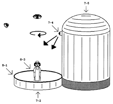
Figure 8 is a perspective view of another embodi~lent of a
holographic display device of Figure 7 with the cylindrical
casing open.
lodes for Carrying Out the invention
In one conventional holographic display configuration shown
in Figur~ 1 marked "Prior Art", a point source of either
coherent or white light 1 - 4 illuminates a rectangular
- 3 -


CA 02277653 1999-07-20
transmission-type hologram 1- 1 from the back in order to project
an orthoscopic real or virtual image 1 -3. In another conventional
holographic display configuration shown in Figure 2 marked "P ri o r
Art", a point source of either coherent or white light 2 - 4
illuminates a rectangular reflection-type hologram 2 - 1 from the
front in order to project an orthoscopic real or virtual image
2-3.
In both of these conventional holographic display
configurations, an orthoscopic real or virtual image is oriented
parallel to the hologram. According to the present invention, a
circular reflection-type hologram has both horizontal and vertical
parallaxes, and an orthoscopic real image is oriented
perpendicular to the hologram.
In one embodi~nt of the invention shown in Figure 3, a
circular reflection-type hologram 3 - 1 is illuminated by a point
source of white light 3 -4 from above in order to project an
orthoscopic real image 3 -3. Means for mounting the point source
of white light 3 - 5 is securely attached to a cylindrical casing
3-2.
Figure 4 shows a sectional view of the holographic display
device along line i- I of Figure 3. A circular mount for
supporting the hologram 4- 1 is attached to the top end of the
cylindrical casing 3 -2. A power supply and a control circuit 4 -3
are securely attached to the cylindrical casing 3 - 2, and are
operably connected to the point source of white light 3 - 4 in order
to illuminate the hologram.
Preferably, the point source of white light 3 - 4 is a
- 4 -


CA 02277653 1999-07-20
high-efficiency light emitting diode. The means for mounting the
point source of white light 3 - 5 may be telescopically or flexibly
extensible so that the angle of incidence may be adjusted.
In another embodiment of the invention shown in Figure 5, a
circular reflection-type hologram 5 - 1 projects an orthoscopic real
image 5 -3. The circular reflection-type hologram 5 - 1 rotates
inside a cylindrical casing 5-2.
Figure 6 shows a sectional view of the holographic display
device along line I - I of Figure 5. A circular mount for
supporting the hologram 6 - 1 has a plurality of legs at the bottom,
comically converging to one point, and is rotatably attached to
the top end of the cylindrical casing 5 -a. A power supply and a
control circuit 6 -3 are securely attached to the cylindrical
casing 5-2, and are operably connected to an electric motor 6 - 4 in
order to rotate the circular mount for supporting the hologram
6-1.
In Figure 7, means for mounting the point source of white
light 7 - 5 is substantially cylindrical and hollow, and has the
same diameter as a cylindrical casing 7 -2 in order to slidably
house the cylindrical casing 7 -2 at the bottom. Figure 8 shows
the cylindrical casing 7 -2 open in order to expose a circular
reflection-type hologram 8 - l, and to p=oject an orthoscopic real
image 8 -3 when illuminated by a point source of white light 7 - 4.
An electric motor may be provided inside the cylindrical casing
7 - 2 in order to rotate the circular reflection-type hologram 8 - 1.
Preferably, the circular reflection-type hologram is
computer-generated and has full colour. The holographic image may
- 5 -


CA 02277653 1999-07-20
be overlaid with a real object having the same shape and size as
the holographic image.
- 6 -

Dessin représentatif
Une figure unique qui représente un dessin illustrant l'invention.
États administratifs

Pour une meilleure compréhension de l'état de la demande ou brevet qui figure sur cette page, la rubrique Mise en garde , et les descriptions de Brevet , États administratifs , Taxes périodiques et Historique des paiements devraient être consultées.

États administratifs

Titre Date
Date de délivrance prévu 2005-01-11
(22) Dépôt 1999-07-20
(41) Mise à la disponibilité du public 2001-01-20
Requête d'examen 2003-05-05
(45) Délivré 2005-01-11
Réputé périmé 2007-07-20

Historique d'abandonnement

Il n'y a pas d'historique d'abandonnement

Historique des paiements

Type de taxes Anniversaire Échéance Montant payé Date payée
Le dépôt d'une demande de brevet 150,00 $ 1999-07-20
Taxe de maintien en état - Demande - nouvelle loi 2 2001-07-20 50,00 $ 2001-05-07
Taxe de maintien en état - Demande - nouvelle loi 3 2002-07-22 50,00 $ 2002-05-07
Requête d'examen 200,00 $ 2003-05-05
Taxe de maintien en état - Demande - nouvelle loi 4 2003-07-21 50,00 $ 2003-05-05
Taxe de maintien en état - Demande - nouvelle loi 5 2004-07-20 75,00 $ 2003-12-23
Taxe de maintien en état - Demande - nouvelle loi 6 2005-07-20 75,00 $ 2003-12-23
Taxe finale 150,00 $ 2004-11-04
Titulaires au dossier

Les titulaires actuels et antérieures au dossier sont affichés en ordre alphabétique.

Titulaires actuels au dossier
SUNATORI, GO SIMON
Titulaires antérieures au dossier
S.O.
Les propriétaires antérieurs qui ne figurent pas dans la liste des « Propriétaires au dossier » apparaîtront dans d'autres documents au dossier.
Documents

Pour visionner les fichiers sélectionnés, entrer le code reCAPTCHA :


Pour visualiser une image, cliquer sur un lien dans la colonne description du document. Pour télécharger l'image (les images), cliquer l'une ou plusieurs cases à cocher dans la première colonne et ensuite cliquer sur le bouton "Télécharger sélection en format PDF (archive Zip)" ou le bouton "Télécharger sélection (en un fichier PDF fusionné)".

Liste des documents de brevet publiés et non publiés sur la BDBC .

Si vous avez des difficultés à accéder au contenu, veuillez communiquer avec le Centre de services à la clientèle au 1-866-997-1936, ou envoyer un courriel au Centre de service à la clientèle de l'OPIC.


Description du
Document 
Date
(yyyy-mm-dd) 
Nombre de pages   Taille de l'image (Ko) 
Revendications 1999-07-20 3 83
Dessins représentatifs 2001-01-05 1 10
Abrégé 1999-07-20 1 27
Dessins 1999-07-20 8 78
Description 1999-07-20 6 191
Page couverture 2001-01-05 1 39
Revendications 2004-05-03 3 82
Dessins représentatifs 2004-12-08 1 12
Page couverture 2004-12-08 2 45
Correspondance 1999-08-19 1 1
Cession 1999-07-20 2 45
Poursuite-Amendment 2003-05-05 1 28
Taxes 2003-05-05 1 28
Taxes 2001-05-07 1 21
Poursuite-Amendment 2004-03-17 3 98
Poursuite-Amendment 2004-05-03 6 222
Correspondance 2004-11-04 1 23