Language selection

Search

Patent 2281232 Summary

Third-party information liability

Some of the information on this Web page has been provided by external sources. The Government of Canada is not responsible for the accuracy, reliability or currency of the information supplied by external sources. Users wishing to rely upon this information should consult directly with the source of the information. Content provided by external sources is not subject to official languages, privacy and accessibility requirements.

Claims and Abstract availability

Any discrepancies in the text and image of the Claims and Abstract are due to differing posting times. Text of the Claims and Abstract are posted:

  • At the time the application is open to public inspection;
  • At the time of issue of the patent (grant).
(12) Patent: (11) CA 2281232
(54) English Title: PRE-PACKED PRODUCT SHIPMENT AND DISPLAY DEVICE WITH SPRING-BIASED RESTOCKING FEED ARRANGEMENT
(54) French Title: DISPOSITIF D'EXPEDITION ET D'AFFICHAGE DE PRODUITS PRE-EMBALLES AVEC DISPOSITIF A RESSORT DE RECONSTITUTION DU STOCK
Status: Expired
Bibliographic Data
(51) International Patent Classification (IPC):
  • A47F 7/03 (2006.01)
  • A47F 1/12 (2006.01)
  • A47F 7/02 (2006.01)
  • B65D 83/00 (2006.01)
  • B65D 85/62 (2006.01)
(72) Inventors :
  • FILIPAK, EDMUND C. (United States of America)
  • TIEDEMANN, SCOTT (United States of America)
(73) Owners :
  • AMERICAN GREETINGS CORPORATION (United States of America)
(71) Applicants :
  • AMERICAN GREETINGS CORPORATION (United States of America)
(74) Agent: NORTON ROSE FULBRIGHT CANADA LLP/S.E.N.C.R.L., S.R.L.
(74) Associate agent:
(45) Issued: 2005-01-04
(22) Filed Date: 1999-08-31
(41) Open to Public Inspection: 2000-03-03
Examination requested: 2000-05-10
Availability of licence: N/A
(25) Language of filing: English

Patent Cooperation Treaty (PCT): No

(30) Application Priority Data:
Application No. Country/Territory Date
09/146,182 United States of America 1998-09-03

Abstracts

English Abstract

A combined product shipment and display device has a plurality of pre-packed product support structures or cartons in a stacked arrangement within a display container structure which includes a base with sloped feeder ramps which advance successive product-carrying cartons in the stacks to openings in the display container, whereby product is neatly displayed at the exterior of the container. Successive cartons of the stack are advanced to the forward most position by spring urging means upon removal of emptied cartons so that the display maintains a freshly stocked and neat appearance.


French Abstract

Un dispositif combiné d'expédition et d'affichage de produits comporte une pluralité de structures de support de produits pré-emballés ou cartons dans un arrangement empilé dans une structure de conteneur d'affichage qui comprend une base avec des rampes d'alimentation inclinées qui avancent des cartons successifs portant des produits dans les piles vers des ouvertures dans le conteneur d'affichage, le produit étant bien affiché à l'extérieur du conteneur. Des cartons successifs de la pile sont avancés vers la position la plus en avant par un dispositif de contrainte de ressort, lorsque des cartons vides sont retirés, de telle sorte que l'affichage garde une apparence nette et bien remplie.

Claims

Note: Claims are shown in the official language in which they were submitted.


CLAIMS,

1. A retail product shipment and display device
comprising:
a frame structure having at least one compartment
configured to support a product carrying carton, the
compartment having an opening through which a product
carrying carton in the frame structure is accessible,
the frame structure connected to a base which
includes a sloped support surface on which a product
carrying carton in the frame structure rests, the sloped
support surface having a slope toward a compartment opening,
and
means for urging a product carrying carton within
a compartment of the frame structure toward the compartment
opening,
wherein the base includes at least two sloped
support surfaces, and
wherein at least two sloped support surfaces of
the base are sloped in different directions.
2. A retail product shipment and display device
comprising:
a frame structure having at least one compartment
configured to support a product carrying carton, the
compartment having an opening through which a product
carrying carton in the frame structure is accessible,
the frame structure connected to a base which
includes a sloped support surface on which a product
carrying carton in the frame structure rests, the sloped
support surface having a slope toward a compartment opening,
and


-5-


means for urging a product carrying carton within
a compartment of the frame structure toward the compartment
opening,
wherein the means for urging a product carrying
carton within a compartment of the frame structure toward a
compartment opening is connected to a product carrying
carton.

3. A product support and display device comprising:
a frame structure attached to a base,
panels attached to the frame structure to form at
least one compartment within the frame structure and an
opening to the compartment,
the base having a sloped support surface located
within the compartment, the sloped support surface oriented
to slope downward toward the opening to the compartment,
a product support structure adapted to fit within
the compartment and rest upon the sloped support surface,
and
urging means adapted to urge the product support
structure down the sloped support surface and toward the
compartment opening,
wherein the base comprises at least two sloped
support surfaces which slope in different directions.

4. A product support and display device comprising:
a frame structure attached to a base,
panels attached to the frame structure to form at
least one compartment within the frame structure and an
opening to the compartment,
the base having a sloped support surface located
within the compartment, the sloped support surface oriented
to slope downward toward the opening to the compartment,


-6-


a product support structure adapted to fit within
the compartment and rest upon the sloped support surface,
and
urging means adapted to urge the product support
structure down the sloped support surface and toward the
compartment opening,
wherein the product support structure is generally
rectangular and comprises at least one wall with openings
adapted to engage with a portion of a product.
5. A combined product shipment and display device
comprising:
a container having a base with a flat bottom
exterior surface upon which the container can be oriented in
a generally upright position,
an interior compartment to the container adapted
to receive a plurality of product-carrying structures, and
an opening in the container providing access to the interior
compartment,
the base having a sloped interior surface located
within the interior compartment of the container and
oriented to slope downward from a back of the compartment to
the opening to the compartment,
a plurality of product-carrying structures within
the interior compartment of the container resting upon the
sloped interior surface of the base, and
a perimeter at least partially about the opening
to the interior compartment of the container configured to
prevent a product-carrying structure from passing through
the opening.


-7-


6. A combined product shipment and display device
comprising:
a container having a base with a flat bottom
exterior surface upon which the container can be oriented in
a generally upright position,
an interior compartment to the container adapted
to receive a plurality of product-carrying structures, and
an opening in the container providing access to the interior
compartment,
the base having a sloped interior surface located
within the interior compartment of the container and
oriented to slope downward from a back of the compartment to
the opening to the compartment, and
a plurality of product-carrying structures within
the interior compartment of the container resting upon the
sloped interior surface of the base,
wherein the container further comprises a top
opening through which a product-carrying structure can be
removed from the interior compartment of the container.


-8-

Description

Note: Descriptions are shown in the official language in which they were submitted.


CA 02281232 1999-08-31
- - Title of the Invention
PRE-PACKED PRODUCT SHIPMENT AND DISPLAY DEVICE WITH
SPRING-BIASED RESTOCKING FEED ARRANGEMENT
Field of the Invention
The present invention pertains generally to retail product bulk packaging and
display
and, more particularly, to structures which serve as both bulk packages and
store displays for
products .
Backeround of the Invention
Products are often displayed in stores in boxes or other display structures
which also
function as bulk packages of the products. Such structures stand on the floor,
carry a sizable
stock of product, and have graphic display panels which advertise the product.
Shipping
cartons which double as a retail display are advantageous in that unpacking
and stocking of a
separate display is avoided. Also, shipping/display boxes can be easily
recycled or otherwise
discarded when emptied, eliminating the expense of permanent displays.
One disadvantage of combined shipping and display packages is that, because
they are
not intended to be restocked, once the stock is partially or totally depleted,
an entire new
shipment is required to replace the display. Although some structures include
stock storage
compartments, this stock has to be separately placed in the exterior display
panels. What is
lacking is a combined shipping and display device whiich carries additional
stock in pre-loaded
displays, in order to increase the retail display iifespan of the display
without sacrificing the
efficiencies of this type device.
Summary of the Present Invention
The present invention provides a combined product shipping container and
display
device for shipment and display of products in a single: structure. In
accordance with one
aspect of the invention, there is provided a retail product shipment and
display device having
a frame structure having at least one compartment configured to support a
product carrying
carton, the compartment having an opening through which a carton in the frame
structure is
accessible, the frame structure connected to a base which includes a sloped
support surface on
which a carton in the frame structure rests, the sloped support surface having
a slope toward a
compartment opening, and means connected to the frame for urging a carton
within a
compartment of the frame structure toward the compartment opening.
In accordance with another aspect of the invention, there is provided a
product support
and display device which includes a frame structure attached to a base, panels
attached to the
frame structure to form at least one compartment within the frame structure
and an opening to


CA 02281232 2004-O1-08
the compartment, the frame structure attached to a base, the
base having a sloped support surface located within the
compartment, the sloped support surface oriented to slope
downward toward the opening to the compartment, a product
support structure adapted to fit within the compartment and
rest upon the sloped support surface, and urging means
adapted to urge the product support structure down the
sloped support surface and toward the compartment opening.
These and other aspects and objects of the
to invention are herein described in particularized detail with
reference to the accompanying Figures.
Brief Description of the Drawings
In the accompanying Figures:
FIG. 1 is a perspective view of one embodiment of
the retail product shipment and display device of the
present invention;
FIG. 2 is a perspective view of a merchandise
2o support carton which fits within the display device of FIG.
1;
FIG. 3 is a perspective view of an alternate
embodiment of a combined retail product shipment and display
device constructed in accordance with the present invention;
FIG. 4 is an elevation of the combined retail
product shipment and display device of FIG. 3; and
FIG. 5 is a cross-sectional view taken along
cross-section lines 5-5 of FIG. 4.
3o Detailed Description of Preferred and Alternate Embodiments
FIGS. 1 and 2 together illustrate a product
shipment and display device 10 which includes a generally
- 2 -


CA 02281232 2004-O1-08
box-shaped frame structure 12 having side panels 14, a back
panel 16, a hinged top panel 18 which also functions as a
display header when in an upright or opened position as
shown, a channeled cross piece 20 which extends between the
s side panels, and an angled floor or bottom panel or panels
22 which slope toward an opening in the frame structure
which may be, for example, the front or side of the display.
This basic structure is also referred to herein as a
"container". A beam 24 extends across the back panel 16
to between the side panels 14. Attached to the beam 24 are two
spring steel pushers 26 which extend toward the open front
of the display and which are angled slightly downward. A
distal end 28 of the pushers 26 is thus positioned farthest
from the back panel and biased toward the open front of the
is display. A divider 30 also extends from the beam 24 toward
the front of the display, and is vertically aligned with a
floor divider 32. The dividers 30 and 32 define separate
compartments 34 and 36, which may be equal or unequal in
width, within the display structure, with a pusher 26
2o approximately centrally located within each compartment. A
- 2a -


CA 02281232 1999-08-31
mirror 35 may be attached to the cross piece 20 as a convenience in a retail
display
environment. J-channels 38 may be provided at the perimeters of the beam 24
and side panels
14 to hold display or decorative panels.
FIG. 2 illustrates one embodiment of a type of display carton 40, also
referred to herein
as a "product-carrying structure", which may be used in connection with the
described display
device 10. The display carton 40 is a generally rectangular structure with a
front face 42, side
walls 44, and a rear wall not shown. A pattern of apertures 46 is formed in
the front face 42
for insertion of products or pieces of products such a.s the arms of
spectacles or sunglasses.
Although shown with a particular pattern, the carton can of course be
alternately configured to
receive and hold any type of product supportable by the carton, and/or solely
by the front face
42 of the carton. The thickness of the cartons 40, as defined by the width of
side walls 44, is
dimensioned so that a plurality of cartons can be positioned front-to-back in
a stacked
arrangement within each of the compartments 34 and 36, with the front face 42
positioned
within the opening in the frame structure to the compartments. The height of
the cartons is
somewhat greater than the height of the frontal opening in the frame to
thereby retain the
forward most carton within the frame structure. To this end, a lip 37 is
provided across a
bottom edge of the frame to contact a lower portion of the front face of the
forward most
carton. Preferably, a width dimension of the carton :is less than a width of
the frontal opening
of the frame structure so that a carton can be removed through the opening by
lifting it over lip
37.
As merchandise is depleted from the front face 42 of one of the cartons 40,
the carton is
removed from the display out the open top or out the opening. The next carton
40 directly
behind the carton removed is urged to the forwardmc~st position by a pusher 26
or similar
urging means so that merchandise is always displayed at the very front of the
display device
10.
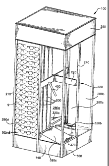
FIGS. 3-5 illustrate an alternate embodiment of the invention which also
provides a pre-
packec~,product shipment and display device 100, which has stacked rows of
product support
and display panels 200, supported within a frame 120, and upon a contoured
pallet 140. In
this particular embodiment, the panels 200 are shown with apertures 210
configured to support
spectacles S. It will be appreciated, however, that panels 200 may be
alternately configured
and otherwise adapted to support any type of product or products to be shipped
and displayed
in the described manner.
The frame 120 includes upper and lower internal joist members 220, which may
intersect orthogonally or at other angles, connected to external stringers 240
which are
generally vertically oriented. The stringers 240 extend upward from a four-
sided base 300,
also referred to herein as a pallet or contoured pallet. At a top end, the
stringers 240 support a
header 260, located generally above the upper joists 2;20. In this embodiment,
the intersecting
joists 220 divide the interior of the device into four quadrants 280a-280d
which correspond to
four contoured quadrants 320a-320d of base 300. Each base quadrant 320 is
angled downward
toward the exterior of the device, so that a lowest point of the base quadrant
is located near the
vertical plane in which the stringers are located. The slope of each base
quadrant 320 is also


CA 02281232 1999-08-31
oriented perpendicular to the slope of the adjacent base quadrants 320, so
that the lowest point
of each base quadrant is positioned at a different side of the four-sided base
300. A lip 370
extends across a bottom edge of each of the quadrant's 320 to retain a lower
portion of the
forward most panel 200. As with the embodiment of FIG. 1, the panels 200 are
preferably
slightly narrower than the frontal opening in the frame 120 to allow removal
through the
opening by simply lifting the panel over the lip 370.
Each of the four quadrants 280a-280d have a depth dimension sufficient to
accommodate a plurality of product support and display panels 200 arranged in
upstanding
rows. The panels 200 in this embodiment are generally rectangular, and with an
individual
depth dimension sufficient to accommodate a portion of product which engages
with the panel,
such as the arms of sunglasses, or any other appendal;e of any product.
Alternatively, the
panels 200 may be simply single-thickness material with through-holes for
attachment of
product. In the preferred form, however, the panels .are configured as a
generally elongate box
out of, for example, corrugated cardboard, with a closed box end which rests
upon the sloping
surface of each base quadrant, and an uninterrupted rear surface. The upright
stringers 240
form an exterior frame for each quadrant in which the: forward-most panel 200
fits to display
products. The top of each frame is bordered by the header 260.
In order to advance the forward-most panel 200 to the front of the respective
'quadrant
and firmly against the frame, a spring 400 is mounted. to extend within each
quadrant down
from the header 260 or joists 220, within each of the quadrants 280a-280d, and
is biased
toward the opening in the frame at the exterior of the display. As multiple
panels 200 are
loaded into a quadrant, the spring 400 contacts the rear wall of the innermost
panel and, in
conjunction with the gravity-assisted feed of the panels by the sloped
quadrant bases 320,
pushes the forward-most panel firmly against the frame. This produces a neat,
structured
appearance to the display and effectively conceals the presence of additional
stock behind the
forward-most panels.
,,
~,~s shown in FIG. 4, one half of each side of xhe display, adjacent to the
exposed panel
200, may be occupied by a graphics panel which also functions to conceal the
side edges of
panels in the adjacent quadrant.
Although the invention has been described witlu reference to certain preferred
and
alternate embodiments, it is to be understood that the invention also includes
modifications and
variations' which may occur to those of skill in the art. For example, and
without limitation,
other means for urging the cartons or product display panels to the openings
of the frame
structure may include coil type springs in various locations within the frame
structure, other
forms of bent metal or plastic springs such as bowed springs or generally
elongate members
having spring-like properties, or similar spring means attached directly to
the cartons. The
pushers may also be integrally formed with the carton's or frame structure.
4

Representative Drawing
A single figure which represents the drawing illustrating the invention.
Administrative Status

For a clearer understanding of the status of the application/patent presented on this page, the site Disclaimer , as well as the definitions for Patent , Administrative Status , Maintenance Fee  and Payment History  should be consulted.

Administrative Status

Title Date
Forecasted Issue Date 2005-01-04
(22) Filed 1999-08-31
(41) Open to Public Inspection 2000-03-03
Examination Requested 2000-05-10
(45) Issued 2005-01-04
Expired 2019-09-03

Abandonment History

There is no abandonment history.

Payment History

Fee Type Anniversary Year Due Date Amount Paid Paid Date
Application Fee $300.00 1999-08-31
Registration of a document - section 124 $100.00 1999-11-25
Request for Examination $400.00 2000-05-10
Maintenance Fee - Application - New Act 2 2001-08-31 $100.00 2001-08-31
Maintenance Fee - Application - New Act 3 2002-09-02 $100.00 2002-08-07
Maintenance Fee - Application - New Act 4 2003-09-02 $100.00 2003-08-25
Maintenance Fee - Application - New Act 5 2004-08-31 $200.00 2004-08-04
Final Fee $300.00 2004-10-18
Maintenance Fee - Patent - New Act 6 2005-08-31 $200.00 2005-08-31
Maintenance Fee - Patent - New Act 7 2006-08-31 $200.00 2006-07-07
Maintenance Fee - Patent - New Act 8 2007-08-31 $200.00 2007-08-16
Maintenance Fee - Patent - New Act 9 2008-09-02 $200.00 2008-08-14
Maintenance Fee - Patent - New Act 10 2009-08-31 $250.00 2009-08-14
Maintenance Fee - Patent - New Act 11 2010-08-31 $250.00 2010-06-04
Maintenance Fee - Patent - New Act 12 2011-08-31 $250.00 2011-06-03
Maintenance Fee - Patent - New Act 13 2012-08-31 $250.00 2012-06-13
Maintenance Fee - Patent - New Act 14 2013-09-03 $250.00 2013-06-11
Maintenance Fee - Patent - New Act 15 2014-09-02 $450.00 2014-06-17
Maintenance Fee - Patent - New Act 16 2015-08-31 $450.00 2015-06-03
Maintenance Fee - Patent - New Act 17 2016-08-31 $450.00 2016-08-09
Maintenance Fee - Patent - New Act 18 2017-08-31 $450.00 2017-06-02
Maintenance Fee - Patent - New Act 19 2018-08-31 $450.00 2018-07-31
Owners on Record

Note: Records showing the ownership history in alphabetical order.

Current Owners on Record
AMERICAN GREETINGS CORPORATION
Past Owners on Record
FILIPAK, EDMUND C.
TIEDEMANN, SCOTT
Past Owners that do not appear in the "Owners on Record" listing will appear in other documentation within the application.
Documents

To view selected files, please enter reCAPTCHA code :


To view images, click a link in the Document Description column. To download the documents, select one or more checkboxes in the first column and then click the "Download Selected in PDF format (Zip Archive)" or the "Download Selected as Single PDF" button.

List of published and non-published patent-specific documents on the CPD .

If you have any difficulty accessing content, you can call the Client Service Centre at 1-866-997-1936 or send them an e-mail at CIPO Client Service Centre.


Document
Description 
Date
(yyyy-mm-dd) 
Number of pages   Size of Image (KB) 
Representative Drawing 2000-02-15 1 15
Cover Page 2000-02-15 1 45
Description 2004-01-08 5 275
Claims 2004-01-08 4 130
Drawings 2004-01-08 3 112
Description 1999-08-31 4 267
Claims 1999-08-31 3 138
Drawings 1999-08-31 4 107
Abstract 1999-08-31 1 17
Representative Drawing 2004-12-02 1 22
Cover Page 2004-12-02 1 50
Correspondence 1999-09-23 1 2
Assignment 1999-08-31 3 123
Correspondence 1999-11-15 1 45
Assignment 1999-11-25 6 292
Assignment 1999-08-31 4 168
Correspondence 1999-12-15 1 1
Prosecution-Amendment 2000-05-10 1 56
Prosecution-Amendment 2000-08-31 3 113
Prosecution-Amendment 2003-07-10 2 72
Prosecution-Amendment 2004-01-08 11 366
Correspondence 2004-10-18 1 34