Language selection

Search

Patent 2282993 Summary

Third-party information liability

Some of the information on this Web page has been provided by external sources. The Government of Canada is not responsible for the accuracy, reliability or currency of the information supplied by external sources. Users wishing to rely upon this information should consult directly with the source of the information. Content provided by external sources is not subject to official languages, privacy and accessibility requirements.

Claims and Abstract availability

Any discrepancies in the text and image of the Claims and Abstract are due to differing posting times. Text of the Claims and Abstract are posted:

  • At the time the application is open to public inspection;
  • At the time of issue of the patent (grant).
(12) Patent: (11) CA 2282993
(54) English Title: SPRING SHANK COULTER WHEEL ASSEMBLY
(54) French Title: MACHINE A CULTIVER DISPOSANT DE COUTRE ET DE FOURCHES A RESSORT
Status: Expired
Bibliographic Data
(51) International Patent Classification (IPC):
  • A01B 35/28 (2006.01)
  • A01B 15/18 (2006.01)
  • A01B 21/08 (2006.01)
  • A01B 23/06 (2006.01)
  • A01B 61/04 (2006.01)
(72) Inventors :
  • MCILHARGEY, JOSEPH F. (Canada)
(73) Owners :
  • SALFORD GROUP INC. (Not Available)
(71) Applicants :
  • MCILHARGEY, JOSEPH F. (Canada)
(74) Agent: DENNISON ASSOCIATES
(74) Associate agent:
(45) Issued: 2007-04-24
(22) Filed Date: 1999-09-22
(41) Open to Public Inspection: 2001-03-22
Examination requested: 2004-07-16
Availability of licence: N/A
(25) Language of filing: English

Patent Cooperation Treaty (PCT): No

(30) Application Priority Data: None

Abstracts

English Abstract

A coulter wheel assembly for mounting to a farm implement having a frame. The assembly includes a vertical shank having a coil spring at substantially its mid-point and upper and lower shank members extending therefrom. The upper shank member is attached to the frame by means of a mounting bracket and the lower shank member is attached to a rotatable hub. A coulter wheel for engagement of the soil is mounted on the hub. The coulter wheel assembly is used, for example, with no-till planting equipment in order to prepare the soil prior to seed introduction. In operation, the coulter wheel rotates along the ground, thereby penetrating the soil, and is permitted to deflect in response to impact with obstructions by means of the coil spring; the coulter wheel then returns to its original path, thereby providing a uniformly prepared soil surface and preventing damage to the coulter wheel assembly or the implement.


French Abstract

Un ensemble de roue de semis pour le montage d'un appareil agricole ayant un châssis. L'ensemble comprend une tige verticale ayant un ressort hélicoïdal sensiblement à son point médian et des éléments inférieur et supérieur de tige s'étendant à partir de celui-ci. L'élément supérieur de tige est fixé au châssis au moyen d'un support de montage et l'élément inférieur de tige est fixé à un moyeu rotatif. Une roue de semis pour l'engagement du sol est montée sur le moyeu. L'ensemble de roue de semis est utilisé, par exemple, avec un équipement de semis de plantation en vue de préparer le sol avant la mise en place des semences. En fonctionnement, la roue de semis tourne sur le sol, de manière à pénétrer dans le sol, et est autorisée à dévier en réponse à l'impact dû à des obstacles au moyen du ressort hélicoïdal ; la roue de semis revient ensuite à son trajet d'origine, pour obtenir une surface du sol préparée de manière uniforme et éviter des dommages à l'ensemble de roue de semis ou à l'appareil agricole.

Claims

Note: Claims are shown in the official language in which they were submitted.


5

Claims:

1. A coulter wheel assembly for attachment to the frame of a farm implement,
said assembly comprising: a coil spring element and a coulter wheel element;
said coil spring element having a coil spring portion having shank ends
extending
outwardly and substantially tangentially to said spring at each end thereof;
said
coulter wheel element having a rotatable hub concentrically mounted to a
coulter
wheel; wherein one of said shank ends is attached to said frame and the other
said shank end is attached to said hub.

2. The coulter wheel assembly of claim 1, wherein said coil spring element is
in substantially vertical alignment with said coulter wheel element.

3. The coulter wheel assembly of claim 1 or 2, wherein said coil spring
portion includes a plurality of parallel coils.

4. The coulter wheel assembly of any one of claims 1 to 3, wherein said
attachment of said shank end to said frame is by means of a bracket, said
bracket fixedly attached to a lateral surface of said frame member and having
a
slit with an aperture for passing one of said ends of said shank therethrough.

5. The coulter wheel assembly of any one of claims 1 to 4, wherein said
attachment of said shank end to said hub is by means of a shaft extending
outwardly from the center of said hub, said shaft including an aperture for
receiving one end of said shank therethrough.

6. The coulter wheel assembly of any one of claims 1 to 5, wherein said
coulter wheel element rotates along the ground, thereby causing said coulter
wheel to penetrate the soil.


Description

Note: Descriptions are shown in the official language in which they were submitted.


CA 02282993 2004-07-16
SPRING SHANK COULTER WHEEL ASSEMBLY
Field of the Invention
The present invention relates to a coulter wheel assembly for soil
preparation. Specifically, the invention relates to a coulter wheel assembly
used
with no-till planting equipment.
Background of the Invention
No-till or conservation tillage methods were designed to prevent the soil
erosion problems associated with previous cultivation methods. These methods
cultivate the minimal amount of soil required for the proper placement of
seeds.
Certain no-till methods employ the use of rotatable coulter wheels in the
preparation of seedbed furrows. The coulter wheels engage the soil and the
movement of the equipment rotates the wheels, which penetrate the surface in
order to cut and mix the soil. However, in operation, the path of the wheel is
often impeded by various obstructions such as stones or stubble from the
previous crop. These obstructions can cause the coulter wheel to be upwardly
deflected, disengaging the wheel from contact with the soil and creating a non-

uniformly prepared soil surface. The impact may also shock the coulter wheel
assembly and impart a loading to the shank that can potentially damage the
assembly or the farm implement to which it is attached.
Summary of the Invention
The present invention is designed to overcome the disadvantages
associated with the prior art devices mentioned above. As such, an object of
the
invention is to provide an improved coulter wheel assembly that is quiet in
operation, durable, simple in design and requiring minimal maintenance.

CA 02282993 2004-07-16
2
An additional object of the invention is to provide a coulter wheel assembly
with superior shock loading characteristics. Such a design advantageously
ensures optimal soil penetration depth and uniformity by promoting straight-
line
coulter travel. In addition, the shock loading characteristics of the present
invention provide a uniformly prepared soil surface by ensuring minimal
disturbance to the soil surface out of the direct path of the coulter wheel.
The objects of the present invention are achieved through use of a coulter
wheel assembly comprising a fluted coulter wheel rotatably mounted to a spring
tine by means of rotatable hub. In operation, the coulter wheel assembly is
attached to a farm implement by means of a mounting bracket.
Brief Description of the Drawings
The objects and advantages of the invention as discussed above will be
further understood in light of the following description of the preferred
embodiments that will be described in conjunction with the accompanying
drawings in which:
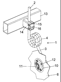
Figure 1 - is a perspective view of the coulter wheel assembly according to
the
present invention;
Figure 2 - is another perspective view of the coulter wheel assembly according
to
the present invention which is complementary to the view shown in Figure 1;
Figure 3 - is a perspective top view of the coulter wheel assembly according
to
the present invention;
Figure 4 - is a perspective side view of the coulter wheel assembly according
to
the present invention; and,
Figure 5 - is a perspective end view of the coulter wheel assembly according
the
present invention.

CA 02282993 2004-07-16
3
Description of Preferred Embodiments
Referring specifically to Figures 1, 2, and 5 a shank, generally shown at 1,
is substantially circular-shaped in cross-section and comprises upper (2) and
lower (3) shank members. Between the shank member several loops of a coil
spring (4) are centrally located, to provide flexibility to the shank. In the
preferred
embodiment shown, the shank includes three substantially vertical loops (4).
However, the number of loops can vary without departing from the spirit of the
invention.
Referring to Figures 1, 2 and 4, a rotatable hub (5) attaches the rotatable
coulter wheel (6) to the lower shank member (3) as described hereinafter. The
hub (5) comprises a flat circular plate (7) with an integrally formed,
centrally
located cylindrical shaft (8). The distal end of the shaft (8) is provided
with an
aperture (9) through which the lower shank (3) is inserted and suitably
secured.
The centrally located aperture of the fluted coulter wheel (6) is attached to
the flat circular plate (7) of the hub. A flat circular ring is located
between the
coulter wheel and the hub bearing cap retainer. The inner most diameter of the
ring corresponds to the diameter of the wheel aperture. The hub bearing cap
retainer (11 ) functions to securely fasten the ring (10), wheel (6) and hub
(5)
together by means of mounting bolts (12). The bolts are threadingly engaged
through corresponding holes located in the cap retainer and the hub.
Referring to Figures 1, 2 and 3, the coulter wheel assembly is adapted for
connection to a farm implement having a frame (13) by means of a mounting
bracket (14) welded to the frame. The bracket (14) is secured to the lateral
surface of the frame such that the coulter wheel assembly is held
substantially
vertical. The upper shank member (2) passes through a circular aperture slit
(15)
located at the distal end of the mounting bracket (14). Once the arm is place,
bolts (16) are passed through corresponding apertures at the distal end of the

CA 02282993 2004-07-16
4
bracket. The bolts are securely fastened by corresponding nuts, thereby
drawing
the slit closed and engaging the upper shank member with the aperture..
In use, as the farm implement moves forward, its motion rotates the coulter
wheel along the ground, thereby penetrating the soil to the desired depth.
When
the wheel encounters an obstruction, the flexibility provided by the spring
allows
the wheel to maintain a substantially continuous path along the soil by
causing
the wheel to deflect in response to the obstruction.
From the foregoing, it will be seen that this invention is one well adapted to
attain all the ends and objects hereinabove set forth together with other
advantages which are obvious and which are inherent to the structure.
It will be understood that certain features and sub-combinations are of
utility and may be employed without reference to other features and sub-
combinations. This is contemplated by and is within the scope of the claims.
Since many possible embodiments may be made of the invention without
departing from the scope of the thereof, it is to be understood that all
matter
herein set forth of shown in the accompanying drawings is to be interpreted as
illustrative and not in a limiting sense.

Representative Drawing
A single figure which represents the drawing illustrating the invention.
Administrative Status

For a clearer understanding of the status of the application/patent presented on this page, the site Disclaimer , as well as the definitions for Patent , Administrative Status , Maintenance Fee  and Payment History  should be consulted.

Administrative Status

Title Date
Forecasted Issue Date 2007-04-24
(22) Filed 1999-09-22
(41) Open to Public Inspection 2001-03-22
Examination Requested 2004-07-16
(45) Issued 2007-04-24
Expired 2019-09-23

Abandonment History

There is no abandonment history.

Payment History

Fee Type Anniversary Year Due Date Amount Paid Paid Date
Application Fee $150.00 1999-09-22
Maintenance Fee - Application - New Act 2 2001-09-24 $50.00 2001-07-26
Registration of a document - section 124 $100.00 2002-05-03
Maintenance Fee - Application - New Act 3 2002-09-23 $100.00 2002-09-04
Maintenance Fee - Application - New Act 4 2003-09-22 $100.00 2003-09-10
Request for Examination $800.00 2004-07-16
Maintenance Fee - Application - New Act 5 2004-09-22 $200.00 2004-07-16
Maintenance Fee - Application - New Act 6 2005-09-22 $200.00 2005-08-25
Expired 2019 - Corrective payment/Section 78.6 $200.00 2006-09-21
Maintenance Fee - Application - New Act 7 2006-09-22 $200.00 2006-09-21
Final Fee $300.00 2007-02-07
Maintenance Fee - Patent - New Act 8 2007-09-24 $200.00 2007-08-28
Maintenance Fee - Patent - New Act 9 2008-09-22 $200.00 2008-08-21
Maintenance Fee - Patent - New Act 10 2009-09-22 $250.00 2009-09-11
Maintenance Fee - Patent - New Act 11 2010-09-22 $250.00 2010-08-16
Registration of a document - section 124 $100.00 2011-08-11
Maintenance Fee - Patent - New Act 12 2011-09-22 $250.00 2011-09-14
Registration of a document - section 124 $100.00 2011-09-29
Maintenance Fee - Patent - New Act 13 2012-09-24 $250.00 2012-08-30
Maintenance Fee - Patent - New Act 14 2013-09-23 $250.00 2013-09-13
Registration of a document - section 124 $100.00 2013-11-22
Maintenance Fee - Patent - New Act 15 2014-09-22 $450.00 2014-09-03
Maintenance Fee - Patent - New Act 16 2015-09-22 $450.00 2015-08-18
Maintenance Fee - Patent - New Act 17 2016-09-22 $450.00 2016-08-17
Maintenance Fee - Patent - New Act 18 2017-09-22 $450.00 2017-07-25
Maintenance Fee - Patent - New Act 19 2018-09-24 $450.00 2018-09-05
Owners on Record

Note: Records showing the ownership history in alphabetical order.

Current Owners on Record
SALFORD GROUP INC.
Past Owners on Record
3908283 CANADA INC.
MCILHARGEY, JOSEPH F.
SALFORD FARM MACHINERY LTD.
Past Owners that do not appear in the "Owners on Record" listing will appear in other documentation within the application.
Documents

To view selected files, please enter reCAPTCHA code :


To view images, click a link in the Document Description column. To download the documents, select one or more checkboxes in the first column and then click the "Download Selected in PDF format (Zip Archive)" or the "Download Selected as Single PDF" button.

List of published and non-published patent-specific documents on the CPD .

If you have any difficulty accessing content, you can call the Client Service Centre at 1-866-997-1936 or send them an e-mail at CIPO Client Service Centre.


Document
Description 
Date
(yyyy-mm-dd) 
Number of pages   Size of Image (KB) 
Representative Drawing 2007-04-04 1 9
Abstract 1999-09-22 1 11
Description 1999-09-22 5 151
Claims 1999-09-22 1 22
Drawings 1999-09-22 2 50
Cover Page 2007-04-04 1 41
Representative Drawing 2001-03-06 1 7
Cover Page 2001-03-06 1 26
Abstract 2004-07-16 1 24
Description 2004-07-16 4 153
Claims 2004-07-16 1 37
Drawings 2004-07-16 2 35
Prosecution-Amendment 2006-09-21 3 92
Correspondence 2006-10-03 1 15
Correspondence 2006-10-03 1 19
Assignment 1999-09-22 4 94
Assignment 2002-05-03 4 135
Fees 2003-09-10 1 37
Correspondence 2006-10-06 1 16
Fees 2001-07-26 1 42
Fees 2002-09-04 1 41
Fees 2004-07-16 3 88
Prosecution-Amendment 2004-07-16 16 549
Fees 2005-08-25 2 69
Correspondence 2006-09-20 2 64
Correspondence 2007-02-07 1 37
Assignment 2011-08-11 8 444
Correspondence 2011-09-19 1 19
Assignment 2011-09-26 2 66
Fees 2011-09-14 1 38
Assignment 2011-09-29 4 177
Fees 2012-08-30 4 176
Assignment 2013-11-22 11 433
Assignment 2013-12-16 2 49
Fees 2013-09-13 3 100
Assignment 2013-12-04 2 48
Correspondence 2014-01-07 1 19
Assignment 2014-03-05 1 39
Fees 2014-09-03 1 33
Maintenance Fee Payment 2015-08-18 4 199