Sélection de la langue

Search

Sommaire du brevet 2282993 

Énoncé de désistement de responsabilité concernant l'information provenant de tiers

Une partie des informations de ce site Web a été fournie par des sources externes. Le gouvernement du Canada n'assume aucune responsabilité concernant la précision, l'actualité ou la fiabilité des informations fournies par les sources externes. Les utilisateurs qui désirent employer cette information devraient consulter directement la source des informations. Le contenu fourni par les sources externes n'est pas assujetti aux exigences sur les langues officielles, la protection des renseignements personnels et l'accessibilité.

Disponibilité de l'Abrégé et des Revendications

L'apparition de différences dans le texte et l'image des Revendications et de l'Abrégé dépend du moment auquel le document est publié. Les textes des Revendications et de l'Abrégé sont affichés :

  • lorsque la demande peut être examinée par le public;
  • lorsque le brevet est émis (délivrance).
(12) Brevet: (11) CA 2282993
(54) Titre français: MACHINE A CULTIVER DISPOSANT DE COUTRE ET DE FOURCHES A RESSORT
(54) Titre anglais: SPRING SHANK COULTER WHEEL ASSEMBLY
Statut: Périmé
Données bibliographiques
(51) Classification internationale des brevets (CIB):
  • A01B 35/28 (2006.01)
  • A01B 15/18 (2006.01)
  • A01B 21/08 (2006.01)
  • A01B 23/06 (2006.01)
  • A01B 61/04 (2006.01)
(72) Inventeurs :
  • MCILHARGEY, JOSEPH F. (Canada)
(73) Titulaires :
  • SALFORD GROUP INC. (Non disponible)
(71) Demandeurs :
  • MCILHARGEY, JOSEPH F. (Canada)
(74) Agent: DENNISON ASSOCIATES
(74) Co-agent:
(45) Délivré: 2007-04-24
(22) Date de dépôt: 1999-09-22
(41) Mise à la disponibilité du public: 2001-03-22
Requête d'examen: 2004-07-16
Licence disponible: S.O.
(25) Langue des documents déposés: Anglais

Traité de coopération en matière de brevets (PCT): Non

(30) Données de priorité de la demande: S.O.

Abrégés

Abrégé français

Un ensemble de roue de semis pour le montage d'un appareil agricole ayant un châssis. L'ensemble comprend une tige verticale ayant un ressort hélicoïdal sensiblement à son point médian et des éléments inférieur et supérieur de tige s'étendant à partir de celui-ci. L'élément supérieur de tige est fixé au châssis au moyen d'un support de montage et l'élément inférieur de tige est fixé à un moyeu rotatif. Une roue de semis pour l'engagement du sol est montée sur le moyeu. L'ensemble de roue de semis est utilisé, par exemple, avec un équipement de semis de plantation en vue de préparer le sol avant la mise en place des semences. En fonctionnement, la roue de semis tourne sur le sol, de manière à pénétrer dans le sol, et est autorisée à dévier en réponse à l'impact dû à des obstacles au moyen du ressort hélicoïdal ; la roue de semis revient ensuite à son trajet d'origine, pour obtenir une surface du sol préparée de manière uniforme et éviter des dommages à l'ensemble de roue de semis ou à l'appareil agricole.


Abrégé anglais

A coulter wheel assembly for mounting to a farm implement having a frame. The assembly includes a vertical shank having a coil spring at substantially its mid-point and upper and lower shank members extending therefrom. The upper shank member is attached to the frame by means of a mounting bracket and the lower shank member is attached to a rotatable hub. A coulter wheel for engagement of the soil is mounted on the hub. The coulter wheel assembly is used, for example, with no-till planting equipment in order to prepare the soil prior to seed introduction. In operation, the coulter wheel rotates along the ground, thereby penetrating the soil, and is permitted to deflect in response to impact with obstructions by means of the coil spring; the coulter wheel then returns to its original path, thereby providing a uniformly prepared soil surface and preventing damage to the coulter wheel assembly or the implement.

Revendications

Note : Les revendications sont présentées dans la langue officielle dans laquelle elles ont été soumises.


5

Claims:

1. A coulter wheel assembly for attachment to the frame of a farm implement,
said assembly comprising: a coil spring element and a coulter wheel element;
said coil spring element having a coil spring portion having shank ends
extending
outwardly and substantially tangentially to said spring at each end thereof;
said
coulter wheel element having a rotatable hub concentrically mounted to a
coulter
wheel; wherein one of said shank ends is attached to said frame and the other
said shank end is attached to said hub.

2. The coulter wheel assembly of claim 1, wherein said coil spring element is
in substantially vertical alignment with said coulter wheel element.

3. The coulter wheel assembly of claim 1 or 2, wherein said coil spring
portion includes a plurality of parallel coils.

4. The coulter wheel assembly of any one of claims 1 to 3, wherein said
attachment of said shank end to said frame is by means of a bracket, said
bracket fixedly attached to a lateral surface of said frame member and having
a
slit with an aperture for passing one of said ends of said shank therethrough.

5. The coulter wheel assembly of any one of claims 1 to 4, wherein said
attachment of said shank end to said hub is by means of a shaft extending
outwardly from the center of said hub, said shaft including an aperture for
receiving one end of said shank therethrough.

6. The coulter wheel assembly of any one of claims 1 to 5, wherein said
coulter wheel element rotates along the ground, thereby causing said coulter
wheel to penetrate the soil.


Description

Note : Les descriptions sont présentées dans la langue officielle dans laquelle elles ont été soumises.

CA 02282993 2004-07-16
SPRING SHANK COULTER WHEEL ASSEMBLY
Field of the Invention
The present invention relates to a coulter wheel assembly for soil
preparation. Specifically, the invention relates to a coulter wheel assembly
used
with no-till planting equipment.
Background of the Invention
No-till or conservation tillage methods were designed to prevent the soil
erosion problems associated with previous cultivation methods. These methods
cultivate the minimal amount of soil required for the proper placement of
seeds.
Certain no-till methods employ the use of rotatable coulter wheels in the
preparation of seedbed furrows. The coulter wheels engage the soil and the
movement of the equipment rotates the wheels, which penetrate the surface in
order to cut and mix the soil. However, in operation, the path of the wheel is
often impeded by various obstructions such as stones or stubble from the
previous crop. These obstructions can cause the coulter wheel to be upwardly
deflected, disengaging the wheel from contact with the soil and creating a non-

uniformly prepared soil surface. The impact may also shock the coulter wheel
assembly and impart a loading to the shank that can potentially damage the
assembly or the farm implement to which it is attached.
Summary of the Invention
The present invention is designed to overcome the disadvantages
associated with the prior art devices mentioned above. As such, an object of
the
invention is to provide an improved coulter wheel assembly that is quiet in
operation, durable, simple in design and requiring minimal maintenance.

CA 02282993 2004-07-16
2
An additional object of the invention is to provide a coulter wheel assembly
with superior shock loading characteristics. Such a design advantageously
ensures optimal soil penetration depth and uniformity by promoting straight-
line
coulter travel. In addition, the shock loading characteristics of the present
invention provide a uniformly prepared soil surface by ensuring minimal
disturbance to the soil surface out of the direct path of the coulter wheel.
The objects of the present invention are achieved through use of a coulter
wheel assembly comprising a fluted coulter wheel rotatably mounted to a spring
tine by means of rotatable hub. In operation, the coulter wheel assembly is
attached to a farm implement by means of a mounting bracket.
Brief Description of the Drawings
The objects and advantages of the invention as discussed above will be
further understood in light of the following description of the preferred
embodiments that will be described in conjunction with the accompanying
drawings in which:
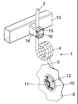
Figure 1 - is a perspective view of the coulter wheel assembly according to
the
present invention;
Figure 2 - is another perspective view of the coulter wheel assembly according
to
the present invention which is complementary to the view shown in Figure 1;
Figure 3 - is a perspective top view of the coulter wheel assembly according
to
the present invention;
Figure 4 - is a perspective side view of the coulter wheel assembly according
to
the present invention; and,
Figure 5 - is a perspective end view of the coulter wheel assembly according
the
present invention.

CA 02282993 2004-07-16
3
Description of Preferred Embodiments
Referring specifically to Figures 1, 2, and 5 a shank, generally shown at 1,
is substantially circular-shaped in cross-section and comprises upper (2) and
lower (3) shank members. Between the shank member several loops of a coil
spring (4) are centrally located, to provide flexibility to the shank. In the
preferred
embodiment shown, the shank includes three substantially vertical loops (4).
However, the number of loops can vary without departing from the spirit of the
invention.
Referring to Figures 1, 2 and 4, a rotatable hub (5) attaches the rotatable
coulter wheel (6) to the lower shank member (3) as described hereinafter. The
hub (5) comprises a flat circular plate (7) with an integrally formed,
centrally
located cylindrical shaft (8). The distal end of the shaft (8) is provided
with an
aperture (9) through which the lower shank (3) is inserted and suitably
secured.
The centrally located aperture of the fluted coulter wheel (6) is attached to
the flat circular plate (7) of the hub. A flat circular ring is located
between the
coulter wheel and the hub bearing cap retainer. The inner most diameter of the
ring corresponds to the diameter of the wheel aperture. The hub bearing cap
retainer (11 ) functions to securely fasten the ring (10), wheel (6) and hub
(5)
together by means of mounting bolts (12). The bolts are threadingly engaged
through corresponding holes located in the cap retainer and the hub.
Referring to Figures 1, 2 and 3, the coulter wheel assembly is adapted for
connection to a farm implement having a frame (13) by means of a mounting
bracket (14) welded to the frame. The bracket (14) is secured to the lateral
surface of the frame such that the coulter wheel assembly is held
substantially
vertical. The upper shank member (2) passes through a circular aperture slit
(15)
located at the distal end of the mounting bracket (14). Once the arm is place,
bolts (16) are passed through corresponding apertures at the distal end of the

CA 02282993 2004-07-16
4
bracket. The bolts are securely fastened by corresponding nuts, thereby
drawing
the slit closed and engaging the upper shank member with the aperture..
In use, as the farm implement moves forward, its motion rotates the coulter
wheel along the ground, thereby penetrating the soil to the desired depth.
When
the wheel encounters an obstruction, the flexibility provided by the spring
allows
the wheel to maintain a substantially continuous path along the soil by
causing
the wheel to deflect in response to the obstruction.
From the foregoing, it will be seen that this invention is one well adapted to
attain all the ends and objects hereinabove set forth together with other
advantages which are obvious and which are inherent to the structure.
It will be understood that certain features and sub-combinations are of
utility and may be employed without reference to other features and sub-
combinations. This is contemplated by and is within the scope of the claims.
Since many possible embodiments may be made of the invention without
departing from the scope of the thereof, it is to be understood that all
matter
herein set forth of shown in the accompanying drawings is to be interpreted as
illustrative and not in a limiting sense.

Dessin représentatif
Une figure unique qui représente un dessin illustrant l'invention.
États administratifs

Pour une meilleure compréhension de l'état de la demande ou brevet qui figure sur cette page, la rubrique Mise en garde , et les descriptions de Brevet , États administratifs , Taxes périodiques et Historique des paiements devraient être consultées.

États administratifs

Titre Date
Date de délivrance prévu 2007-04-24
(22) Dépôt 1999-09-22
(41) Mise à la disponibilité du public 2001-03-22
Requête d'examen 2004-07-16
(45) Délivré 2007-04-24
Expiré 2019-09-23

Historique d'abandonnement

Il n'y a pas d'historique d'abandonnement

Historique des paiements

Type de taxes Anniversaire Échéance Montant payé Date payée
Le dépôt d'une demande de brevet 150,00 $ 1999-09-22
Taxe de maintien en état - Demande - nouvelle loi 2 2001-09-24 50,00 $ 2001-07-26
Enregistrement de documents 100,00 $ 2002-05-03
Taxe de maintien en état - Demande - nouvelle loi 3 2002-09-23 100,00 $ 2002-09-04
Taxe de maintien en état - Demande - nouvelle loi 4 2003-09-22 100,00 $ 2003-09-10
Requête d'examen 800,00 $ 2004-07-16
Taxe de maintien en état - Demande - nouvelle loi 5 2004-09-22 200,00 $ 2004-07-16
Taxe de maintien en état - Demande - nouvelle loi 6 2005-09-22 200,00 $ 2005-08-25
Expiré 2019 - Paiement rectificatif/L'article 78.6 200,00 $ 2006-09-21
Taxe de maintien en état - Demande - nouvelle loi 7 2006-09-22 200,00 $ 2006-09-21
Taxe finale 300,00 $ 2007-02-07
Taxe de maintien en état - brevet - nouvelle loi 8 2007-09-24 200,00 $ 2007-08-28
Taxe de maintien en état - brevet - nouvelle loi 9 2008-09-22 200,00 $ 2008-08-21
Taxe de maintien en état - brevet - nouvelle loi 10 2009-09-22 250,00 $ 2009-09-11
Taxe de maintien en état - brevet - nouvelle loi 11 2010-09-22 250,00 $ 2010-08-16
Enregistrement de documents 100,00 $ 2011-08-11
Taxe de maintien en état - brevet - nouvelle loi 12 2011-09-22 250,00 $ 2011-09-14
Enregistrement de documents 100,00 $ 2011-09-29
Taxe de maintien en état - brevet - nouvelle loi 13 2012-09-24 250,00 $ 2012-08-30
Taxe de maintien en état - brevet - nouvelle loi 14 2013-09-23 250,00 $ 2013-09-13
Enregistrement de documents 100,00 $ 2013-11-22
Taxe de maintien en état - brevet - nouvelle loi 15 2014-09-22 450,00 $ 2014-09-03
Taxe de maintien en état - brevet - nouvelle loi 16 2015-09-22 450,00 $ 2015-08-18
Taxe de maintien en état - brevet - nouvelle loi 17 2016-09-22 450,00 $ 2016-08-17
Taxe de maintien en état - brevet - nouvelle loi 18 2017-09-22 450,00 $ 2017-07-25
Taxe de maintien en état - brevet - nouvelle loi 19 2018-09-24 450,00 $ 2018-09-05
Titulaires au dossier

Les titulaires actuels et antérieures au dossier sont affichés en ordre alphabétique.

Titulaires actuels au dossier
SALFORD GROUP INC.
Titulaires antérieures au dossier
3908283 CANADA INC.
MCILHARGEY, JOSEPH F.
SALFORD FARM MACHINERY LTD.
Les propriétaires antérieurs qui ne figurent pas dans la liste des « Propriétaires au dossier » apparaîtront dans d'autres documents au dossier.
Documents

Pour visionner les fichiers sélectionnés, entrer le code reCAPTCHA :


Pour visualiser une image, cliquer sur un lien dans la colonne description du document. Pour télécharger l'image (les images), cliquer l'une ou plusieurs cases à cocher dans la première colonne et ensuite cliquer sur le bouton "Télécharger sélection en format PDF (archive Zip)" ou le bouton "Télécharger sélection (en un fichier PDF fusionné)".

Liste des documents de brevet publiés et non publiés sur la BDBC .

Si vous avez des difficultés à accéder au contenu, veuillez communiquer avec le Centre de services à la clientèle au 1-866-997-1936, ou envoyer un courriel au Centre de service à la clientèle de l'OPIC.


Description du
Document 
Date
(yyyy-mm-dd) 
Nombre de pages   Taille de l'image (Ko) 
Dessins représentatifs 2007-04-04 1 9
Abrégé 1999-09-22 1 11
Description 1999-09-22 5 151
Revendications 1999-09-22 1 22
Dessins 1999-09-22 2 50
Page couverture 2007-04-04 1 41
Dessins représentatifs 2001-03-06 1 7
Page couverture 2001-03-06 1 26
Abrégé 2004-07-16 1 24
Description 2004-07-16 4 153
Revendications 2004-07-16 1 37
Dessins 2004-07-16 2 35
Poursuite-Amendment 2006-09-21 3 92
Correspondance 2006-10-03 1 15
Correspondance 2006-10-03 1 19
Cession 1999-09-22 4 94
Cession 2002-05-03 4 135
Taxes 2003-09-10 1 37
Correspondance 2006-10-06 1 16
Taxes 2001-07-26 1 42
Taxes 2002-09-04 1 41
Taxes 2004-07-16 3 88
Poursuite-Amendment 2004-07-16 16 549
Taxes 2005-08-25 2 69
Correspondance 2006-09-20 2 64
Correspondance 2007-02-07 1 37
Cession 2011-08-11 8 444
Correspondance 2011-09-19 1 19
Cession 2011-09-26 2 66
Taxes 2011-09-14 1 38
Cession 2011-09-29 4 177
Taxes 2012-08-30 4 176
Cession 2013-11-22 11 433
Cession 2013-12-16 2 49
Taxes 2013-09-13 3 100
Cession 2013-12-04 2 48
Correspondance 2014-01-07 1 19
Cession 2014-03-05 1 39
Taxes 2014-09-03 1 33
Paiement de taxe périodique 2015-08-18 4 199