Some of the information on this Web page has been provided by external sources. The Government of Canada is not responsible for the accuracy, reliability or currency of the information supplied by external sources. Users wishing to rely upon this information should consult directly with the source of the information. Content provided by external sources is not subject to official languages, privacy and accessibility requirements.
Any discrepancies in the text and image of the Claims and Abstract are due to differing posting times. Text of the Claims and Abstract are posted:
| (12) Patent: | (11) CA 2324214 |
|---|---|
| (54) English Title: | THREAD JOINT FOR PERCUSSIVE DRILLING |
| (54) French Title: | JOINT A FILETAGE POUR FORAGE A PERCUSSION |
| Status: | Expired |
| (51) International Patent Classification (IPC): |
|
|---|---|
| (72) Inventors : |
|
| (73) Owners : |
|
| (71) Applicants : |
|
| (74) Agent: | GOWLING WLG (CANADA) LLP |
| (74) Associate agent: | |
| (45) Issued: | 2007-07-31 |
| (86) PCT Filing Date: | 1999-03-19 |
| (87) Open to Public Inspection: | 1999-09-30 |
| Examination requested: | 2004-01-28 |
| Availability of licence: | N/A |
| (25) Language of filing: | English |
| Patent Cooperation Treaty (PCT): | Yes |
|---|---|
| (86) PCT Filing Number: | PCT/SE1999/000431 |
| (87) International Publication Number: | WO1999/049176 |
| (85) National Entry: | 2000-09-18 |
| (30) Application Priority Data: | ||||||
|---|---|---|---|---|---|---|
|
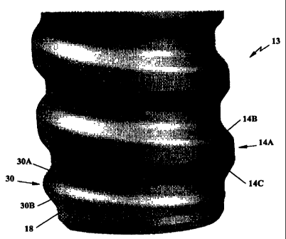
The present invention relates to a thread
joint, a male portion, a female portion and
a method for manufacturing a product for
percussive drilling. The threaded connection
comprises at least one substantially cylindrical
external thread and a substantially cylindrical
internal thread. The external thread is
provided on a spigot (13) of a drill string
component. The thread comprises thread ends
(30) provided in connection with an associated
full profile thread (14A). Said thread
comprises thread flanks (30A, 30B, 14B, 14C).
At least one of the substantially cylindrical
threads comprises at least one thread end (30)
the shape of which differs from the shape of
the full profile thread (14A). Each thread flank
(30A, 30B) of the thread end (30) has a profile,
which differs from the profile of the
associated flanks (14B, 14C) of the full profile
thread (14A).
Cette invention se rapporte à un raccord fileté, à une pièce mâle, à une pièce femelle et à un procédé de fabrication d'un produit pour forage par percussion. Ce raccord fileté comprend au moins un filetage externe essentiellement cylindrique et un filetage interne essentiellement cylindrique. Le filetage externe est ménagé sur un goujon (13) d'un constituant du train de tiges de forage. Ce filetage comporte des extrémités (30) coopérant avec un filetage à profil droit associé (14A). Ce filetage comporte également des flancs (30A, 30B, 14B, 14C). Au moins l'un des filetages essentiellement cylindriques comporte au moins une extrémité (30) dont la forme diffère de la forme du filetage à profil droit (14A). Chaque flanc (30A, 30B) de l'extrémité (30) du filetage présente un profil qui diffère du profil des flancs associés (14B, 14C) du filetage à profil droit (14A).
Note: Claims are shown in the official language in which they were submitted.
Note: Descriptions are shown in the official language in which they were submitted.
For a clearer understanding of the status of the application/patent presented on this page, the site Disclaimer , as well as the definitions for Patent , Administrative Status , Maintenance Fee and Payment History should be consulted.
| Title | Date |
|---|---|
| Forecasted Issue Date | 2007-07-31 |
| (86) PCT Filing Date | 1999-03-19 |
| (87) PCT Publication Date | 1999-09-30 |
| (85) National Entry | 2000-09-18 |
| Examination Requested | 2004-01-28 |
| (45) Issued | 2007-07-31 |
| Expired | 2019-03-19 |
There is no abandonment history.
Note: Records showing the ownership history in alphabetical order.
| Current Owners on Record |
|---|
| SANDVIK INTELLECTUAL PROPERTY AB |
| Past Owners on Record |
|---|
| LILJEBRAND, PER-OLOF |
| OLSSON, URBAN |
| SANDVIK AB |
| SANDVIK INTELLECTUAL PROPERTY HB |

