Sélection de la langue

Search

Sommaire du brevet 2324214 

Énoncé de désistement de responsabilité concernant l'information provenant de tiers

Une partie des informations de ce site Web a été fournie par des sources externes. Le gouvernement du Canada n'assume aucune responsabilité concernant la précision, l'actualité ou la fiabilité des informations fournies par les sources externes. Les utilisateurs qui désirent employer cette information devraient consulter directement la source des informations. Le contenu fourni par les sources externes n'est pas assujetti aux exigences sur les langues officielles, la protection des renseignements personnels et l'accessibilité.

Disponibilité de l'Abrégé et des Revendications

L'apparition de différences dans le texte et l'image des Revendications et de l'Abrégé dépend du moment auquel le document est publié. Les textes des Revendications et de l'Abrégé sont affichés :

  • lorsque la demande peut être examinée par le public;
  • lorsque le brevet est émis (délivrance).
(12) Brevet: (11) CA 2324214
(54) Titre français: JOINT A FILETAGE POUR FORAGE A PERCUSSION
(54) Titre anglais: THREAD JOINT FOR PERCUSSIVE DRILLING
Statut: Périmé
Données bibliographiques
(51) Classification internationale des brevets (CIB):
  • E21B 17/042 (2006.01)
(72) Inventeurs :
  • LILJEBRAND, PER-OLOF (Suède)
  • OLSSON, URBAN (Suède)
(73) Titulaires :
  • SANDVIK INTELLECTUAL PROPERTY AB (Suède)
(71) Demandeurs :
  • SANDVIK AB (Suède)
(74) Agent: GOWLING WLG (CANADA) LLP
(74) Co-agent:
(45) Délivré: 2007-07-31
(86) Date de dépôt PCT: 1999-03-19
(87) Mise à la disponibilité du public: 1999-09-30
Requête d'examen: 2004-01-28
Licence disponible: S.O.
(25) Langue des documents déposés: Anglais

Traité de coopération en matière de brevets (PCT): Oui
(86) Numéro de la demande PCT: PCT/SE1999/000431
(87) Numéro de publication internationale PCT: WO1999/049176
(85) Entrée nationale: 2000-09-18

(30) Données de priorité de la demande:
Numéro de la demande Pays / territoire Date
9800995-4 Suède 1998-03-24

Abrégés

Abrégé français

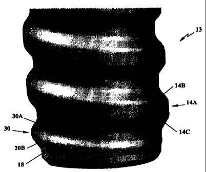
Cette invention se rapporte à un raccord fileté, à une pièce mâle, à une pièce femelle et à un procédé de fabrication d'un produit pour forage par percussion. Ce raccord fileté comprend au moins un filetage externe essentiellement cylindrique et un filetage interne essentiellement cylindrique. Le filetage externe est ménagé sur un goujon (13) d'un constituant du train de tiges de forage. Ce filetage comporte des extrémités (30) coopérant avec un filetage à profil droit associé (14A). Ce filetage comporte également des flancs (30A, 30B, 14B, 14C). Au moins l'un des filetages essentiellement cylindriques comporte au moins une extrémité (30) dont la forme diffère de la forme du filetage à profil droit (14A). Chaque flanc (30A, 30B) de l'extrémité (30) du filetage présente un profil qui diffère du profil des flancs associés (14B, 14C) du filetage à profil droit (14A).


Abrégé anglais


The present invention relates to a thread
joint, a male portion, a female portion and
a method for manufacturing a product for
percussive drilling. The threaded connection
comprises at least one substantially cylindrical
external thread and a substantially cylindrical
internal thread. The external thread is
provided on a spigot (13) of a drill string
component. The thread comprises thread ends
(30) provided in connection with an associated
full profile thread (14A). Said thread
comprises thread flanks (30A, 30B, 14B, 14C).
At least one of the substantially cylindrical
threads comprises at least one thread end (30)
the shape of which differs from the shape of
the full profile thread (14A). Each thread flank
(30A, 30B) of the thread end (30) has a profile,
which differs from the profile of the
associated flanks (14B, 14C) of the full profile
thread (14A).

Revendications

Note : Les revendications sont présentées dans la langue officielle dans laquelle elles ont été soumises.


6
Claims

1. A thread joint for percussive drilling including at least one substantially

cylindrical external thread (14) and a substantially cylindrical internal
thread
(12), said external thread (14) being provided on a spigot (13) intended to
constitute an integral part of a first drill string component (10), said
threads
comprising thread ends (30) provided in connection with an associated full
profile thread (14A), said threads (12,14) comprising thread flanks
(30A,30B,14B,14C),
characterized in that at least one of the substantially cylindrical threads
(12,14) comprises at least one thread end (30) the shape of which differing
from the full profile thread (14A) shape and that both thread flanks (30A,30B)
of
the thread end (30) have a profile which differs from the profile of the
connected flanks (14B,14C) of the full profile thread (14A).

2. The thread joint according to claim 1, wherein the thread end (30) has a
more rounded cross-section than the full profile thread (14A) and wherein both

the cross-sectional area and the height of the thread end (30) increase from
the
start of the thread end in direction circumferentially towards the associated
full
profile thread (14A) and in that the flanks (30A,30B) of the thread end (30)
are
substantially identical.

3. Thread joint according to claim 1 or 2, wherein the smallest radius (R1,R2)
of
the thread end (30) is at least as large as the smallest radius (R3) of the
full
profile thread (14A).

4. Thread joint according to claim 1, 2 or 3, wherein the smallest radius
(R1,R2) of the thread end (30) is bigger than 0.2 mm.

5. Male portion for forming a part of a thread joint for percussive drilling,
wherein the male portion (13) includes at least one substantially cylindrical
external thread (14), said external thread (14) being provided on a spigot
(13)


7
intended to constitute an integral part of a first drill string component
(10), said
thread (14) comprising thread ends (30) provided in connection to an
associated full profile thread (14A), said external thread (14) comprising
thread
flanks (30A,30B,14B,14C),
characterized in that the substantially cylindrical thread (14) comprises
at least one thread end (30) the shape of which differs from the full profile
thread (14A) shape and that both thread flanks (30A,30B) of the thread end
(30) have a profile which differ from the profile of the associated flanks
(14B,14C) of the full profile thread (14A).

6. Male portion according to claim 5, wherein both the cross-sectional area
and
the height of the thread end (30) increases from the beginning of the thread
ends circumferentially in direction towards the associated full profile thread

(14A) and that the smallest radius (R1,R2) of the thread end (30) is bigger
than
0.2 mm and that the smallest radius (R1,R2) of the thread end (30) is at least

as large as the smallest radius (R3) of the full profile thread (14A).

7. Female portion for forming a part of a thread joint for percussive
drilling,
wherein the female portion (11) includes at least one substantially
cylindrical
internal thread (12), said internal thread (12) being provided in an end
intended
to constitute an integral part of a first drill string component (10), said
thread
comprising thread ends (30) provided in connection with an associated full
profile thread (14A), said internal thread (12) comprising thread flanks
(30A,30B,14B,14C),
characterized in that the substantially cylindrical thread (12) comprises
at least one thread end (30) the shape of which differs from the full profile
thread (14A) shape and that both thread flanks (30A,30B) of the thread end
(30) have a profile which differs from the profile of the connected flanks
(14B,14C) of the full profile thread (14A).

8. Female portion according to claim 7, wherein both the cross-sectional area
and the height of the thread end (30) increases from the thread end start


8
circumferentially in direction towards the associated full profile thread
(14A) and
that the smallest radius (R1,R2) of the thread end (30) is bigger than 0.2 mm
and of that the smallest radius (R1,R2) of the thread end (30) is at least as
large as the smallest radius (R3) of the full profile thread (14A).

9. Method for manufacturing a product having a thread for forming a part of a
thread joint for percussive drilling, wherein the thread includes at least one

thread end (30) having flanks (30A,30B) and a full profile thread (14A) having

flanks (14B,14C), wherein the method comprises the following steps:
a) provide a blank of metal in a machine for metallic machining,
b) provide a threading tool in the machine,
c) co-ordinate longitudinal and lateral feed of the tool with rotational
movement
of the blank about an axis of rotation (CL) such that the thread is generated
on
the blank,
characterized in that step c) further comprises the step of adjusting the
threading tool to profile the thread end (30) such that each thread flank
(30A,30B) of the thread end (30) obtains a profile which differs from the
profile
of the associated flanks (14B,14C) of the full profile thread (14).

10. Method according to claim 9, wherein the method further comprises the
step of:
d) heat-treating at least the cut thread.

Description

Note : Les descriptions sont présentées dans la langue officielle dans laquelle elles ont été soumises.


CA 02324214 2006-09-12

THREAD JOINT FOR PERCUSSIVE DRILLING
Background of the invention
The present invention relates to a thread joint, a male portion, a female
portion
and a method for manufacturing the product.

Prior art
In a conventional thread joint between two components in a rock drilling
equipment for percussive drilling one normally uses cut male and female
threads, see for example SE-B-469,602. At manufacturing of such a male
thread a blank of steel is formed, which comprises a thick part which ends
connect to a clearance surface or a clearance groove with less diameter for to
receive at least portions of the threading tool and to a often conical free
end.
Subsequently, the tool's lateral and longitudinal feed are coordinated with
the
rotational movement of the thick portion such as to generate the thread in a
conventional manner during at least one pass. Sharp edges are formed at the
entrance and exit of the thread due to the geometry's of the clearance groove
and the free end surface. Corresponding sharp edges are formed at threading
of a female thread. The sharp edges makes the male and female threads
damaging each other foremost at the free end of the respective drilling
element
during mounting and dismounting of the joint. In addition, the threads are
case
hardened and the sharp edges become hardened too much such that the sharp
edges define the area for the deepest case depth of the thread. Results from
the hardening show cracking and fatigue in these areas during drilling, and
therefore the lifespan of the joint becomes relatively short. Another
conventional thread joint between two components in a rock drilling equipment
for percussive drilling and experience cracking is shown in EP-A2-220 147
wherein the thread end is cut away to maintain a full thread profile to the
end of
the thread.


CA 02324214 2000-09-18

WO 99/49176 PCT/SE99/00431
2
Obiects of the invention
One object of the present invention is to provide a thread joint of the above-
indicated type in which a good tool life is attained.

Another object of the present invention is to provide a thread joint including
entrances and exits with substantially the same case depth as in the rest of
the
thread joint.

Still another object of the present invention is to provide a thread joint the
parts
of which do not damage each other during mounting and dismounting.

Still another object of the present invention is to provide strong male and
female portions.
Still another object of the present invention is to provide a method for
manufacturing rock drilling products that have strong thread starts.
Short description of the drawinas
The objects of the invention are realized by a thread joint, a male portion, a
female portion and a method for manufacturing a product that have the features
indicated in the subsequent claims. Below, one embodiment of the invention
will
be described with reference to the enclosed drawings wherein,
Fig. 1 shows a cross-section of an end of a female portion according to the
present invention; Figs. 2A and 2B show an end of a male portion according to
the present invention in a side view. Fig. 3 shows a partly sectioned view of
a
thread joint according to the invention. Fig. 4 shows an end view of the male
portion. Figs. 5A-5D show various cross-sections of a thread entrance.

Detailed description of the invention
The drill rod 10 for percussive drilling shown in Figs. 1, 2A and 2B is
provided
with a sleeve-shaped part or a female portion 11 according to the present


CA 02324214 2000-09-18

WO 99/49176 PCT/SE99/00431
3
invention at one end having a female thread or internal thread 12. The female
portion 11 constitutes an integral part of the drill rod 10. At the other end
the
drill rod 10 is formed with a spigot or male portion 13 according to the
present
invention equipped with a male thread or external thread 14. The drill rod
further has a through-going flush channel 15, through which a flush medium,
generally air or water, is conducted. The female portion 11 bottom forms a
ring-
shaped abutment surface 16, which at mounting of two drill rods 10 is intended
to abut against a corresponding annular abutment surface 17 at the free end of
the shank 13 of the other drill rod.
In Figs. 4 and 5A-5D are shown an end view of the male portion and different
cross-sections I-IV of an entrance thread 30 and a finished full profile
thread in
shape of a trapezoidal thread 14A. The thread end 30 has a more rounded
cross-section than the full profile thread 14A. The cross-sections {-IV are
taken
with 90 :s partition and towards the center axis CL of the male portion. At
the
section I according to Fig. 5A, here taken as reference at 0 , the threading
tool
does not reach the envelope surface of the thick part of the steel body and
the
entrance thread still has not started to be cut but instead is provided an end
surface 18 only, which is defined by a straight line in the section I. The end
surface 18 is usually conical. The entrance thread 30 describes at the section
11
according to Fig. 5B, at 90 :s difference from the section I counter-
clockwise, a
path which resembles a bell curve or the cross section of a symmetrical ridge
has a smallest radius R1 which is bigger than 0.2 mm and a height h1. The
entrance thread 30 comprises substantially identical flanks 30A and 30B. In
the
section according to Fig. 5C, at 90 :s difference from the section 11 counter-
clockwise, the cross-sectional area has grown further, whereby the ridge and
the flanks have a smallest radius R2 which is bigger than 0.2 mm and a height
h2. In Fig. 5D according to the section I, i.e. 360 from the above-described
section I the entrance thread has entirely surpassed into a full profile
thread or
finished trapezoidal thread 14A with a smallest radius R3 that is bigger than
0.2
mm and a height h3. The full profile thread 14A has substantially identical
flanks 14B and 14C. It can be seen from Figs. 5A-5D that both the cross-


CA 02324214 2000-09-18

WO 99/49176 PCT/SE99/00431
4
sectional area and the height of the entrance thread 30 increase from the
start
between the sections I and II circumferentially to the finished thread 14A
while
the smallest radius R1-R3 is not less than 0.2 mm. In case the finished thread
is a trapezoidal thread 14A then the smallest radius R2 of the entrance thread
30 in the section III is greater than the smallest radius R3 of the
trapezoidal
thread 14A. Since sharp edges do not exist at entrances and exits 30 of the
thread 14 the hardening depth at heat-treatment, for example case hardening,
becomes essentialiy constant along the entire thread, and therefor cracks and
fatigue is avoided in these areas. At conventional cut threads one of the
thread
flanks at the thread end always has the same profile as the full profile
thread
except for being somewhat lower while both thread flanks 30A, 30B of the
current thread end 30 have profiles which differ from the profile of the
connected flanks 14B and 14C, respectively, of the full profile thread 14A,
see
Figs. 5B and 5D. Preferably there are provided two entrances and two exits at
the thread ends.

A corresponding soft profile is attained at the entrances and exits of the
female
thread 12.

When the threaded connection, Fig. 3, of two drill rods 10 according to the
present invention is mounted, the free end of the male portion 13 will enter
at
the area of the free end of the female portion. In most cases the rods must be
rotated relative to each other during insertion such that the threads can come
into engagement with each other. Before threading starts the soft thread ends
prevent that the rods damage each other. Subsequently, the rods can be
rotated until the front surface 17 of the rod abuts against the bottom 16. The
full
profile threads 12 and 14 are designed in a conventional manner such that
when they have been mounted abutment arises only at the straight flank
portions 14B and the corresponding flanks at the female portion. Consequently,
contact between curved parties or between peaks and bottoms do not occur. At
tests the thread joint according to the present invention has exhibited at
least
doubled tool life compared to conventional thread joints.


= CA 02324214 2006-09-12

Turning of the thread 12 or 14 is made in the following manner. In a
conventional manner the lateral and longitudinal feed and cutting depth of the
tool is co-ordinated with the rotational movement of the thick portion such
that a
5 thread is generated during at least one passage. This is attained by a
thread
master or via a threading program in a lathe. Having the threading tool
deciding
the thread profile substantially without being influenced by connecting
clearances thereby attains soft entrances and exits at the thread ends.
Subsequently at least the cut thread is heat treated for example through case
hardening.

Conceivable modifications of the invention
Altematively, the rod is provided in the shape of a driil tube and can also
comprise shoulder abutment of the type that is illustrated in US-A-4,968,068.
In
the embodiment disclosed herein, a trapezoidal thread is shown but it is
implicit
that the invention can be utilized for alI rock drilling threads, such as for
example
rope threads. The female portion or the male portion may altematively be
integrated with a rock driil bit instead of with a drill rod or a drill rod.
The
principles of the invention can be applied also at a thread joint between a
shank
adapter and the drill rod and between two drill rods with a loose threaded
sleeve.

Also in other respects the invention can be freely varied within the scope of
the
appended claims.

Dessin représentatif
Une figure unique qui représente un dessin illustrant l'invention.
États administratifs

Pour une meilleure compréhension de l'état de la demande ou brevet qui figure sur cette page, la rubrique Mise en garde , et les descriptions de Brevet , États administratifs , Taxes périodiques et Historique des paiements devraient être consultées.

États administratifs

Titre Date
Date de délivrance prévu 2007-07-31
(86) Date de dépôt PCT 1999-03-19
(87) Date de publication PCT 1999-09-30
(85) Entrée nationale 2000-09-18
Requête d'examen 2004-01-28
(45) Délivré 2007-07-31
Expiré 2019-03-19

Historique d'abandonnement

Il n'y a pas d'historique d'abandonnement

Historique des paiements

Type de taxes Anniversaire Échéance Montant payé Date payée
Enregistrement de documents 100,00 $ 2000-09-18
Le dépôt d'une demande de brevet 300,00 $ 2000-09-18
Taxe de maintien en état - Demande - nouvelle loi 2 2001-03-19 100,00 $ 2001-02-20
Taxe de maintien en état - Demande - nouvelle loi 3 2002-03-19 100,00 $ 2002-02-21
Taxe de maintien en état - Demande - nouvelle loi 4 2003-03-19 100,00 $ 2003-02-25
Taxe de maintien en état - Demande - nouvelle loi 5 2004-03-19 200,00 $ 2004-01-09
Requête d'examen 800,00 $ 2004-01-28
Taxe de maintien en état - Demande - nouvelle loi 6 2005-03-21 200,00 $ 2005-02-21
Enregistrement de documents 100,00 $ 2005-05-27
Enregistrement de documents 100,00 $ 2005-08-11
Taxe de maintien en état - Demande - nouvelle loi 7 2006-03-20 200,00 $ 2006-02-16
Taxe de maintien en état - Demande - nouvelle loi 8 2007-03-19 200,00 $ 2007-02-16
Taxe finale 300,00 $ 2007-05-14
Taxe de maintien en état - brevet - nouvelle loi 9 2008-03-19 200,00 $ 2008-02-08
Taxe de maintien en état - brevet - nouvelle loi 10 2009-03-19 250,00 $ 2009-02-12
Taxe de maintien en état - brevet - nouvelle loi 11 2010-03-19 250,00 $ 2010-02-18
Taxe de maintien en état - brevet - nouvelle loi 12 2011-03-21 250,00 $ 2011-02-17
Taxe de maintien en état - brevet - nouvelle loi 13 2012-03-19 250,00 $ 2012-02-08
Taxe de maintien en état - brevet - nouvelle loi 14 2013-03-19 250,00 $ 2013-02-13
Taxe de maintien en état - brevet - nouvelle loi 15 2014-03-19 450,00 $ 2014-02-14
Taxe de maintien en état - brevet - nouvelle loi 16 2015-03-19 450,00 $ 2015-02-25
Taxe de maintien en état - brevet - nouvelle loi 17 2016-03-21 450,00 $ 2016-02-24
Taxe de maintien en état - brevet - nouvelle loi 18 2017-03-20 450,00 $ 2017-02-22
Taxe de maintien en état - brevet - nouvelle loi 19 2018-03-19 450,00 $ 2018-02-21
Titulaires au dossier

Les titulaires actuels et antérieures au dossier sont affichés en ordre alphabétique.

Titulaires actuels au dossier
SANDVIK INTELLECTUAL PROPERTY AB
Titulaires antérieures au dossier
LILJEBRAND, PER-OLOF
OLSSON, URBAN
SANDVIK AB
SANDVIK INTELLECTUAL PROPERTY HB
Les propriétaires antérieurs qui ne figurent pas dans la liste des « Propriétaires au dossier » apparaîtront dans d'autres documents au dossier.
Documents

Pour visionner les fichiers sélectionnés, entrer le code reCAPTCHA :


Pour visualiser une image, cliquer sur un lien dans la colonne description du document. Pour télécharger l'image (les images), cliquer l'une ou plusieurs cases à cocher dans la première colonne et ensuite cliquer sur le bouton "Télécharger sélection en format PDF (archive Zip)" ou le bouton "Télécharger sélection (en un fichier PDF fusionné)".

Liste des documents de brevet publiés et non publiés sur la BDBC .

Si vous avez des difficultés à accéder au contenu, veuillez communiquer avec le Centre de services à la clientèle au 1-866-997-1936, ou envoyer un courriel au Centre de service à la clientèle de l'OPIC.


Description du
Document 
Date
(yyyy-mm-dd) 
Nombre de pages   Taille de l'image (Ko) 
Dessins représentatifs 2000-12-14 1 13
Page couverture 2000-12-14 1 67
Abrégé 2000-09-18 1 66
Description 2000-09-18 5 256
Revendications 2000-09-18 3 136
Dessins 2000-09-18 3 85
Description 2006-09-12 5 242
Dessins 2006-09-12 3 46
Dessins représentatifs 2007-07-10 1 20
Page couverture 2007-07-10 2 58
Cession 2000-09-18 4 156
PCT 2000-09-18 9 343
Poursuite-Amendment 2004-01-28 1 35
Poursuite-Amendment 2004-05-26 1 33
Cession 2005-08-11 6 275
Poursuite-Amendment 2006-07-24 2 46
Poursuite-Amendment 2006-09-12 5 133
Cession 2005-05-27 7 209
Poursuite-Amendment 2006-12-06 1 30
Correspondance 2006-12-08 1 18
Correspondance 2007-05-14 2 48