Language selection

Search

Patent 2326425 Summary

Third-party information liability

Some of the information on this Web page has been provided by external sources. The Government of Canada is not responsible for the accuracy, reliability or currency of the information supplied by external sources. Users wishing to rely upon this information should consult directly with the source of the information. Content provided by external sources is not subject to official languages, privacy and accessibility requirements.

Claims and Abstract availability

Any discrepancies in the text and image of the Claims and Abstract are due to differing posting times. Text of the Claims and Abstract are posted:

  • At the time the application is open to public inspection;
  • At the time of issue of the patent (grant).
(12) Patent: (11) CA 2326425
(54) English Title: GAS TURBINE OR JET ENGINE STATOR VANE FRAME
(54) French Title: ARMATURE D'AUBE DE STATOR POUR TURBINE A GAZ OU TURBOREACTEUR
Status: Deemed expired
Bibliographic Data
(51) International Patent Classification (IPC):
  • F01D 9/00 (2006.01)
  • F01D 9/04 (2006.01)
  • F01D 11/00 (2006.01)
(72) Inventors :
  • MANTEIGA, JOHN A. (United States of America)
  • NUSSBAUM, JEFFREY H. (United States of America)
  • NOON, JOHN L. (United States of America)
(73) Owners :
  • GENERAL ELECTRIC COMPANY (United States of America)
(71) Applicants :
  • GENERAL ELECTRIC COMPANY (United States of America)
(74) Agent: CRAIG WILSON AND COMPANY
(74) Associate agent:
(45) Issued: 2007-06-12
(22) Filed Date: 2000-11-23
(41) Open to Public Inspection: 2001-06-07
Examination requested: 2002-11-07
Availability of licence: N/A
(25) Language of filing: English

Patent Cooperation Treaty (PCT): No

(30) Application Priority Data:
Application No. Country/Territory Date
09/456,967 United States of America 1999-12-07

Abstracts

English Abstract

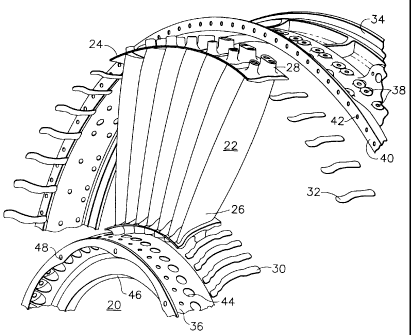
A stator vane frame assembly including an outer structure ring (34), an inner structure ring (36), a set of discrete vanes (22) each connecting the outer structure ring (34) and the inner structure ring (36) forming an inner and outer platforms with neighboring vanes (22) defining a set of flow paths, a set of sealing members (30, 32, 58, 70) contoured to a set of gaps (60) between the set of vanes (22) disposed to sealing the gap (60). A method for applying a sealing member (30, 32, 58, 70) to the gaps (60) between a platform formed resulting from the coupling between vanes (22) including affixing a set of stator vanes (22) on an inner frame and an outer frame, and sealing a set of sealing members (30, 32, 58, 70) on the backside surface of a stator vane frame. The discrete nature of individual vane blade sealed by the sealing members (30, 32, 58, 70) renders the stator vane frame assembly to add a damping effect which increases the fatigue life of the vane (22), and permits the use of lower strength, lighter, and less expensive material.


French Abstract

Cadre d'aube de stator muni d'un anneau de structure extérieur (34), d'un anneau de structure intérieur (36), et d'un ensemble d'aubes distinctes (22), chacune étant reliée à l'anneau de structure extérieur (34) et à l'anneau de structure intérieur (36), formant ainsi des plateformes externes et internes avec les aubes adjacentes (22) et définissant un ensemble de circuits d'écoulement, un ensemble d'éléments d'étanchéité (30, 32, 58, 70) entourant les vides (60) entre les ensembles d'aubes (22), disposés de manière à combler les vides (60). Méthode d'application d'éléments d'étanchéité (30, 32, 58, 70) aux vides (60) entre la plateforme créée par le lien entre les aubes (22), y compris l'application d'un ensemble d'aubes de stator (22) sur un cadre intérieur et un cadre extérieur, et le scellement de l'ensemble d'éléments d'étanchéité (30, 32, 58, 70) sur la surface arrière du cadre d'aube de stator. La nature distincte de chaque aube scellée au moyen des éléments d'étanchéité (30, 32, 58, 70) fait en sorte que le cadre d'aube de stator ajoute un effet tampon qui augmente la période de résistance de l'aube (22) et permet l'utilisation d'un matériau moins résistant, plus léger et moins coûteux.

Claims

Note: Claims are shown in the official language in which they were submitted.


What is claimed:


1. A stator vane assembly comprising:
an outer structure ring including a rim;
an inner structure ring;
a plurality of vanes extending radially from said inner structure ring to
said outer structure ring; each said vane being attached at an inner end to
said inner
structure ring and at an outer end to said outer structure ring, each said
vane including
an inner platform and an outer platform;
a plurality of sealing members positioned across a plurality of gaps
formed between adjacent ones of said inner and outer platforms, each of said
plurality
of sealing members being bonded to said platforms by an adhesive sealant.


2. The assembly of claim 1 wherein said adhesive sealant has
viscous vibration damping characteristics.


3. The assembly of claim 2, said sealant being a room temperature
vulcanizing sealant.


4. The assembly of claim 2 being located within a gas turbine.

5. The assembly of claim 2 being located within a jet engine.


6. The assembly of claim 2 wherein the outer structure ring and the
inner structure ring comprises part of an outlet guide vane frame.


7. The assembly of claim 2 wherein each of the plurality of vanes is
bolted to the outer structure ring and the inner structure ring.


8. The assembly of claim 2, said vanes extending in a flow path,
each said sealing members being bonded to an outer side of said platforms
facing away
from said flow path.


4


9. The assembly of claim 2, each said outer platform having a first
edge abutting and bonded to a first rim of the outer structure ring by
adhesive sealant.


10. The assembly of claim 9, each said outer platform having a
second edge opposite said first edge, said assembly further comprising a
sealing strip
applied to said second edge.


Description

Note: Descriptions are shown in the official language in which they were submitted.


CA 02326425 2000-11-23
13DV 13042

GAS TURBINE OR JET ENGINE STATOR VANE FRAME
BACKGROUND OF THE INVENTION
This invention relates to gas turbine or jet engines, and, more
particularly, to gas turbine or jet engine stator vane frames.
As is known, the inner surface of a compressor casing, in gas turbine
or jet engines, is machined with circumferential T-section grooves to retain
stator
blades therein. Engines also include variable outlet guide vanes to direct
flow
alignment. In this case variable vane bearing seats are formed by radial holes
and
counterbores through circumferential supporting ribs. Stator blades are locked
in the
compressor casing, forming a platform either directly through T-grooves or by
to retaining rings. In order to efficiently use the compressed air flowing
through the
vanes, the casing needs to be suitably sealed. Also, vane vibration results in
platform
deflection, which causes shearing motion relative to separate and integral
part of a
stator vane frame assemble. A gasket is provided around the frames to seal the
air
path. However, the low damping effect of the vane frame can lead to vibratory
stresses which exceed material strength, and which may result in vane cracking
and
other failures.

BRIEF SUMMARY OF THE INVENTION
In an exemplary embodiment of the invention a stator vane frame
assembly includes an outer structure ring, an inner structure ring, a set of
vanes
connecting the outer structure ring and the inner structure ring, that forms
inner and
outer platforms, a set of flow paths, a set of sealing members contoured to a
set of
gaps between the set of vanes disposed to sealing the gap. Also, a spacer in
between
the frame and the vane platform is eliminated in that the sealing members
perform the
function of the spacer.
In addition, vibratory stresses are reduced by the damping effect
caused by the introduction of sealing members disposed to seal individual or
discrete
vanes. Each individual vane is connected together with some other members of
the

1


CA 02326425 2000-11-23
13DV13042

set of vanes. Gaps between the vanes are sealed on the backside by a sealing
member
to enhance a damping effect so that metal fatigue of the relevant metal parts
is
reduced. Also, vane cracking and other failures are reduced as well. In
addition, the
added damping provided by the sealing members increases the fatigue life of
the
vanes, as well as permitting the use of lower strength, lighter, and less
expensive
materials.

BRIEF DESCRIPTION OF THE DRAWINGS
Figure 1 is a partial perspective view of a stator vane from assembly of
the prior art;
Figure 2 is a perspective semi-exploded view of a fan outlet guide vane
frame; and
Figure 3 is a partial perspective view of the outlet guide vane
assembly.

DETAILED DESCRIPTION OF THE INVENTION
Referring to prior art Figure 1, a stator vane frame assembly 10 is
generally shown. Stator vane frame assembly 10 has individual vanes 12 which
are
connected to an inner frame 14 as well as an outer frame 16. A gasket 18 is
rapped
around the outer frame 16. Similarly, another gasket (not shown) may rap
around
inner frame 14. Such a stator vane frame assembly is well known in the art.
Referring to Figure 2, a fan outlet guide vane frame of an exemplary
embodiment or the present invention is generally shown at 20. Individual vanes
22
having integral flowpath platforms 24 form an inner flowpath surface 26 as
well as an
outer flowpath surface 28. A set of inner strips 30 and a set of outer strips
32 seal the
gaps between platforms 24. The set of inner strips 30 and the set of outer
strips 32 are
contoured in such a way that optimum sealing and damping effects are achieved.
The
inner strips 30 and the outer strips 32 are contoured to match the shape of
the
platforms 24 and affixed on the backside of the platforms 24 using a suitable
adhesive
such as a room temperature vulcanizing sealant (e.g., RTV). An outer structure
ring
34 and an inner structure ring 36 have individual vanes 22 bolted thereto. The
outer
2


CA 02326425 2000-11-23
13DV 13042

structure ring 34 has bolting holes 38 for connecting the vanes 22. Similarly,
the
outer structure ring 34 has a side rim 40 for connecting with a neighboring
structure
ring via a set of holes 42. The inner structure ring 36 has a set of bolting
holes 44 for
connecting the vanes 22. Similarly, the inner structure ring 36 has side rim
46 for
connecting with a neighboring structure ring via a set of holes 48.
Referring to Figure 3, an outlet guide vane frame outer ring 50 has
holes 52 for bolting the reciprocal holes 54 on a vane platform 56. An
aluminum
damper strip 58 is bounded by a suitable room temperature vulcanization
sealant to
the vane platform 56 sealing a gap 60 on the vane platform 56. The vane
platform 56
defines a first edge 62 that connects to a first rim 64 of the outer ring 50
via a room
temperature vulcanization sealant bead. The outer ring 50 further defines a
second
rim 66, which has connecting holes 68 for connection with neighboring systems.
In
another embodiment of Figure 3, a sealing strip 70 may be applied to a second
edge
72 of the vane platform 56.
It is to be noted that vane vibration results in platform deflection,
which causes relative shearing motion through the adhesive to the seal strips.
This
relative motion results in viscous damping that absorbs energy. The adhesive
is
suitably chosen for its environmental bonding and viscous damping
characteristics.
The quality of the connecting elements determines an optimum damping state.
Parameters such as the choice of material, thickness, bonded surface area and
a
number of layers are suitably selected to provide the best viscous damping.
While the invention has been described with reference to a preferred
embodiment, it will be understood by those skilled in the art that various
changes may
be made and equivalents may be substituted for elements thereof without
departing
from the scope of the invention. In addition, many modifications may be made
to
adapt a particular situation or material to the teachings of the invention
without
departing from the essential scope thereof. Therefore, it is intended that the
invention
not be limited to the particular embodiment disclosed as the best mode
contemplated
for carrying out this invention, but that the invention will include all
embodiments
falling within the scope of the appended claims.
3

Representative Drawing
A single figure which represents the drawing illustrating the invention.
Administrative Status

For a clearer understanding of the status of the application/patent presented on this page, the site Disclaimer , as well as the definitions for Patent , Administrative Status , Maintenance Fee  and Payment History  should be consulted.

Administrative Status

Title Date
Forecasted Issue Date 2007-06-12
(22) Filed 2000-11-23
(41) Open to Public Inspection 2001-06-07
Examination Requested 2002-11-07
(45) Issued 2007-06-12
Deemed Expired 2017-11-23

Abandonment History

There is no abandonment history.

Payment History

Fee Type Anniversary Year Due Date Amount Paid Paid Date
Registration of a document - section 124 $100.00 2000-11-23
Application Fee $300.00 2000-11-23
Request for Examination $400.00 2002-11-07
Maintenance Fee - Application - New Act 2 2002-11-25 $100.00 2002-11-07
Maintenance Fee - Application - New Act 3 2003-11-24 $100.00 2003-11-06
Maintenance Fee - Application - New Act 4 2004-11-23 $100.00 2004-11-09
Maintenance Fee - Application - New Act 5 2005-11-23 $200.00 2005-11-10
Maintenance Fee - Application - New Act 6 2006-11-23 $200.00 2006-11-03
Final Fee $300.00 2007-03-27
Maintenance Fee - Patent - New Act 7 2007-11-23 $200.00 2007-10-30
Maintenance Fee - Patent - New Act 8 2008-11-24 $200.00 2008-10-30
Maintenance Fee - Patent - New Act 9 2009-11-23 $200.00 2009-10-30
Maintenance Fee - Patent - New Act 10 2010-11-23 $250.00 2010-11-01
Maintenance Fee - Patent - New Act 11 2011-11-23 $250.00 2011-10-31
Maintenance Fee - Patent - New Act 12 2012-11-23 $250.00 2012-10-29
Maintenance Fee - Patent - New Act 13 2013-11-25 $250.00 2013-10-30
Maintenance Fee - Patent - New Act 14 2014-11-24 $250.00 2014-11-17
Maintenance Fee - Patent - New Act 15 2015-11-23 $450.00 2015-11-16
Owners on Record

Note: Records showing the ownership history in alphabetical order.

Current Owners on Record
GENERAL ELECTRIC COMPANY
Past Owners on Record
MANTEIGA, JOHN A.
NOON, JOHN L.
NUSSBAUM, JEFFREY H.
Past Owners that do not appear in the "Owners on Record" listing will appear in other documentation within the application.
Documents

To view selected files, please enter reCAPTCHA code :


To view images, click a link in the Document Description column. To download the documents, select one or more checkboxes in the first column and then click the "Download Selected in PDF format (Zip Archive)" or the "Download Selected as Single PDF" button.

List of published and non-published patent-specific documents on the CPD .

If you have any difficulty accessing content, you can call the Client Service Centre at 1-866-997-1936 or send them an e-mail at CIPO Client Service Centre.


Document
Description 
Date
(yyyy-mm-dd) 
Number of pages   Size of Image (KB) 
Claims 2000-11-23 2 53
Representative Drawing 2001-06-04 1 14
Claims 2002-11-07 2 45
Description 2000-11-23 3 151
Abstract 2000-11-23 1 29
Drawings 2000-11-23 3 64
Cover Page 2001-06-04 1 48
Claims 2006-01-12 2 41
Representative Drawing 2007-05-24 1 20
Cover Page 2007-05-24 1 53
Correspondence 2007-03-27 1 26
Assignment 2000-11-23 4 160
Prosecution-Amendment 2002-11-07 4 100
Prosecution-Amendment 2005-07-15 2 36
Prosecution-Amendment 2006-01-12 3 75