Sélection de la langue

Search

Sommaire du brevet 2326425 

Énoncé de désistement de responsabilité concernant l'information provenant de tiers

Une partie des informations de ce site Web a été fournie par des sources externes. Le gouvernement du Canada n'assume aucune responsabilité concernant la précision, l'actualité ou la fiabilité des informations fournies par les sources externes. Les utilisateurs qui désirent employer cette information devraient consulter directement la source des informations. Le contenu fourni par les sources externes n'est pas assujetti aux exigences sur les langues officielles, la protection des renseignements personnels et l'accessibilité.

Disponibilité de l'Abrégé et des Revendications

L'apparition de différences dans le texte et l'image des Revendications et de l'Abrégé dépend du moment auquel le document est publié. Les textes des Revendications et de l'Abrégé sont affichés :

  • lorsque la demande peut être examinée par le public;
  • lorsque le brevet est émis (délivrance).
(12) Brevet: (11) CA 2326425
(54) Titre français: ARMATURE D'AUBE DE STATOR POUR TURBINE A GAZ OU TURBOREACTEUR
(54) Titre anglais: GAS TURBINE OR JET ENGINE STATOR VANE FRAME
Statut: Réputé périmé
Données bibliographiques
(51) Classification internationale des brevets (CIB):
  • F01D 9/00 (2006.01)
  • F01D 9/04 (2006.01)
  • F01D 11/00 (2006.01)
(72) Inventeurs :
  • MANTEIGA, JOHN A. (Etats-Unis d'Amérique)
  • NUSSBAUM, JEFFREY H. (Etats-Unis d'Amérique)
  • NOON, JOHN L. (Etats-Unis d'Amérique)
(73) Titulaires :
  • GENERAL ELECTRIC COMPANY (Etats-Unis d'Amérique)
(71) Demandeurs :
  • GENERAL ELECTRIC COMPANY (Etats-Unis d'Amérique)
(74) Agent: CRAIG WILSON AND COMPANY
(74) Co-agent:
(45) Délivré: 2007-06-12
(22) Date de dépôt: 2000-11-23
(41) Mise à la disponibilité du public: 2001-06-07
Requête d'examen: 2002-11-07
Licence disponible: S.O.
(25) Langue des documents déposés: Anglais

Traité de coopération en matière de brevets (PCT): Non

(30) Données de priorité de la demande:
Numéro de la demande Pays / territoire Date
09/456,967 Etats-Unis d'Amérique 1999-12-07

Abrégés

Abrégé français

Cadre d'aube de stator muni d'un anneau de structure extérieur (34), d'un anneau de structure intérieur (36), et d'un ensemble d'aubes distinctes (22), chacune étant reliée à l'anneau de structure extérieur (34) et à l'anneau de structure intérieur (36), formant ainsi des plateformes externes et internes avec les aubes adjacentes (22) et définissant un ensemble de circuits d'écoulement, un ensemble d'éléments d'étanchéité (30, 32, 58, 70) entourant les vides (60) entre les ensembles d'aubes (22), disposés de manière à combler les vides (60). Méthode d'application d'éléments d'étanchéité (30, 32, 58, 70) aux vides (60) entre la plateforme créée par le lien entre les aubes (22), y compris l'application d'un ensemble d'aubes de stator (22) sur un cadre intérieur et un cadre extérieur, et le scellement de l'ensemble d'éléments d'étanchéité (30, 32, 58, 70) sur la surface arrière du cadre d'aube de stator. La nature distincte de chaque aube scellée au moyen des éléments d'étanchéité (30, 32, 58, 70) fait en sorte que le cadre d'aube de stator ajoute un effet tampon qui augmente la période de résistance de l'aube (22) et permet l'utilisation d'un matériau moins résistant, plus léger et moins coûteux.


Abrégé anglais

A stator vane frame assembly including an outer structure ring (34), an inner structure ring (36), a set of discrete vanes (22) each connecting the outer structure ring (34) and the inner structure ring (36) forming an inner and outer platforms with neighboring vanes (22) defining a set of flow paths, a set of sealing members (30, 32, 58, 70) contoured to a set of gaps (60) between the set of vanes (22) disposed to sealing the gap (60). A method for applying a sealing member (30, 32, 58, 70) to the gaps (60) between a platform formed resulting from the coupling between vanes (22) including affixing a set of stator vanes (22) on an inner frame and an outer frame, and sealing a set of sealing members (30, 32, 58, 70) on the backside surface of a stator vane frame. The discrete nature of individual vane blade sealed by the sealing members (30, 32, 58, 70) renders the stator vane frame assembly to add a damping effect which increases the fatigue life of the vane (22), and permits the use of lower strength, lighter, and less expensive material.

Revendications

Note : Les revendications sont présentées dans la langue officielle dans laquelle elles ont été soumises.


What is claimed:


1. A stator vane assembly comprising:
an outer structure ring including a rim;
an inner structure ring;
a plurality of vanes extending radially from said inner structure ring to
said outer structure ring; each said vane being attached at an inner end to
said inner
structure ring and at an outer end to said outer structure ring, each said
vane including
an inner platform and an outer platform;
a plurality of sealing members positioned across a plurality of gaps
formed between adjacent ones of said inner and outer platforms, each of said
plurality
of sealing members being bonded to said platforms by an adhesive sealant.


2. The assembly of claim 1 wherein said adhesive sealant has
viscous vibration damping characteristics.


3. The assembly of claim 2, said sealant being a room temperature
vulcanizing sealant.


4. The assembly of claim 2 being located within a gas turbine.

5. The assembly of claim 2 being located within a jet engine.


6. The assembly of claim 2 wherein the outer structure ring and the
inner structure ring comprises part of an outlet guide vane frame.


7. The assembly of claim 2 wherein each of the plurality of vanes is
bolted to the outer structure ring and the inner structure ring.


8. The assembly of claim 2, said vanes extending in a flow path,
each said sealing members being bonded to an outer side of said platforms
facing away
from said flow path.


4


9. The assembly of claim 2, each said outer platform having a first
edge abutting and bonded to a first rim of the outer structure ring by
adhesive sealant.


10. The assembly of claim 9, each said outer platform having a
second edge opposite said first edge, said assembly further comprising a
sealing strip
applied to said second edge.


Description

Note : Les descriptions sont présentées dans la langue officielle dans laquelle elles ont été soumises.


CA 02326425 2000-11-23
13DV 13042

GAS TURBINE OR JET ENGINE STATOR VANE FRAME
BACKGROUND OF THE INVENTION
This invention relates to gas turbine or jet engines, and, more
particularly, to gas turbine or jet engine stator vane frames.
As is known, the inner surface of a compressor casing, in gas turbine
or jet engines, is machined with circumferential T-section grooves to retain
stator
blades therein. Engines also include variable outlet guide vanes to direct
flow
alignment. In this case variable vane bearing seats are formed by radial holes
and
counterbores through circumferential supporting ribs. Stator blades are locked
in the
compressor casing, forming a platform either directly through T-grooves or by
to retaining rings. In order to efficiently use the compressed air flowing
through the
vanes, the casing needs to be suitably sealed. Also, vane vibration results in
platform
deflection, which causes shearing motion relative to separate and integral
part of a
stator vane frame assemble. A gasket is provided around the frames to seal the
air
path. However, the low damping effect of the vane frame can lead to vibratory
stresses which exceed material strength, and which may result in vane cracking
and
other failures.

BRIEF SUMMARY OF THE INVENTION
In an exemplary embodiment of the invention a stator vane frame
assembly includes an outer structure ring, an inner structure ring, a set of
vanes
connecting the outer structure ring and the inner structure ring, that forms
inner and
outer platforms, a set of flow paths, a set of sealing members contoured to a
set of
gaps between the set of vanes disposed to sealing the gap. Also, a spacer in
between
the frame and the vane platform is eliminated in that the sealing members
perform the
function of the spacer.
In addition, vibratory stresses are reduced by the damping effect
caused by the introduction of sealing members disposed to seal individual or
discrete
vanes. Each individual vane is connected together with some other members of
the

1


CA 02326425 2000-11-23
13DV13042

set of vanes. Gaps between the vanes are sealed on the backside by a sealing
member
to enhance a damping effect so that metal fatigue of the relevant metal parts
is
reduced. Also, vane cracking and other failures are reduced as well. In
addition, the
added damping provided by the sealing members increases the fatigue life of
the
vanes, as well as permitting the use of lower strength, lighter, and less
expensive
materials.

BRIEF DESCRIPTION OF THE DRAWINGS
Figure 1 is a partial perspective view of a stator vane from assembly of
the prior art;
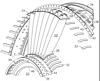
Figure 2 is a perspective semi-exploded view of a fan outlet guide vane
frame; and
Figure 3 is a partial perspective view of the outlet guide vane
assembly.

DETAILED DESCRIPTION OF THE INVENTION
Referring to prior art Figure 1, a stator vane frame assembly 10 is
generally shown. Stator vane frame assembly 10 has individual vanes 12 which
are
connected to an inner frame 14 as well as an outer frame 16. A gasket 18 is
rapped
around the outer frame 16. Similarly, another gasket (not shown) may rap
around
inner frame 14. Such a stator vane frame assembly is well known in the art.
Referring to Figure 2, a fan outlet guide vane frame of an exemplary
embodiment or the present invention is generally shown at 20. Individual vanes
22
having integral flowpath platforms 24 form an inner flowpath surface 26 as
well as an
outer flowpath surface 28. A set of inner strips 30 and a set of outer strips
32 seal the
gaps between platforms 24. The set of inner strips 30 and the set of outer
strips 32 are
contoured in such a way that optimum sealing and damping effects are achieved.
The
inner strips 30 and the outer strips 32 are contoured to match the shape of
the
platforms 24 and affixed on the backside of the platforms 24 using a suitable
adhesive
such as a room temperature vulcanizing sealant (e.g., RTV). An outer structure
ring
34 and an inner structure ring 36 have individual vanes 22 bolted thereto. The
outer
2


CA 02326425 2000-11-23
13DV 13042

structure ring 34 has bolting holes 38 for connecting the vanes 22. Similarly,
the
outer structure ring 34 has a side rim 40 for connecting with a neighboring
structure
ring via a set of holes 42. The inner structure ring 36 has a set of bolting
holes 44 for
connecting the vanes 22. Similarly, the inner structure ring 36 has side rim
46 for
connecting with a neighboring structure ring via a set of holes 48.
Referring to Figure 3, an outlet guide vane frame outer ring 50 has
holes 52 for bolting the reciprocal holes 54 on a vane platform 56. An
aluminum
damper strip 58 is bounded by a suitable room temperature vulcanization
sealant to
the vane platform 56 sealing a gap 60 on the vane platform 56. The vane
platform 56
defines a first edge 62 that connects to a first rim 64 of the outer ring 50
via a room
temperature vulcanization sealant bead. The outer ring 50 further defines a
second
rim 66, which has connecting holes 68 for connection with neighboring systems.
In
another embodiment of Figure 3, a sealing strip 70 may be applied to a second
edge
72 of the vane platform 56.
It is to be noted that vane vibration results in platform deflection,
which causes relative shearing motion through the adhesive to the seal strips.
This
relative motion results in viscous damping that absorbs energy. The adhesive
is
suitably chosen for its environmental bonding and viscous damping
characteristics.
The quality of the connecting elements determines an optimum damping state.
Parameters such as the choice of material, thickness, bonded surface area and
a
number of layers are suitably selected to provide the best viscous damping.
While the invention has been described with reference to a preferred
embodiment, it will be understood by those skilled in the art that various
changes may
be made and equivalents may be substituted for elements thereof without
departing
from the scope of the invention. In addition, many modifications may be made
to
adapt a particular situation or material to the teachings of the invention
without
departing from the essential scope thereof. Therefore, it is intended that the
invention
not be limited to the particular embodiment disclosed as the best mode
contemplated
for carrying out this invention, but that the invention will include all
embodiments
falling within the scope of the appended claims.
3

Dessin représentatif
Une figure unique qui représente un dessin illustrant l'invention.
États administratifs

Pour une meilleure compréhension de l'état de la demande ou brevet qui figure sur cette page, la rubrique Mise en garde , et les descriptions de Brevet , États administratifs , Taxes périodiques et Historique des paiements devraient être consultées.

États administratifs

Titre Date
Date de délivrance prévu 2007-06-12
(22) Dépôt 2000-11-23
(41) Mise à la disponibilité du public 2001-06-07
Requête d'examen 2002-11-07
(45) Délivré 2007-06-12
Réputé périmé 2017-11-23

Historique d'abandonnement

Il n'y a pas d'historique d'abandonnement

Historique des paiements

Type de taxes Anniversaire Échéance Montant payé Date payée
Enregistrement de documents 100,00 $ 2000-11-23
Le dépôt d'une demande de brevet 300,00 $ 2000-11-23
Requête d'examen 400,00 $ 2002-11-07
Taxe de maintien en état - Demande - nouvelle loi 2 2002-11-25 100,00 $ 2002-11-07
Taxe de maintien en état - Demande - nouvelle loi 3 2003-11-24 100,00 $ 2003-11-06
Taxe de maintien en état - Demande - nouvelle loi 4 2004-11-23 100,00 $ 2004-11-09
Taxe de maintien en état - Demande - nouvelle loi 5 2005-11-23 200,00 $ 2005-11-10
Taxe de maintien en état - Demande - nouvelle loi 6 2006-11-23 200,00 $ 2006-11-03
Taxe finale 300,00 $ 2007-03-27
Taxe de maintien en état - brevet - nouvelle loi 7 2007-11-23 200,00 $ 2007-10-30
Taxe de maintien en état - brevet - nouvelle loi 8 2008-11-24 200,00 $ 2008-10-30
Taxe de maintien en état - brevet - nouvelle loi 9 2009-11-23 200,00 $ 2009-10-30
Taxe de maintien en état - brevet - nouvelle loi 10 2010-11-23 250,00 $ 2010-11-01
Taxe de maintien en état - brevet - nouvelle loi 11 2011-11-23 250,00 $ 2011-10-31
Taxe de maintien en état - brevet - nouvelle loi 12 2012-11-23 250,00 $ 2012-10-29
Taxe de maintien en état - brevet - nouvelle loi 13 2013-11-25 250,00 $ 2013-10-30
Taxe de maintien en état - brevet - nouvelle loi 14 2014-11-24 250,00 $ 2014-11-17
Taxe de maintien en état - brevet - nouvelle loi 15 2015-11-23 450,00 $ 2015-11-16
Titulaires au dossier

Les titulaires actuels et antérieures au dossier sont affichés en ordre alphabétique.

Titulaires actuels au dossier
GENERAL ELECTRIC COMPANY
Titulaires antérieures au dossier
MANTEIGA, JOHN A.
NOON, JOHN L.
NUSSBAUM, JEFFREY H.
Les propriétaires antérieurs qui ne figurent pas dans la liste des « Propriétaires au dossier » apparaîtront dans d'autres documents au dossier.
Documents

Pour visionner les fichiers sélectionnés, entrer le code reCAPTCHA :


Pour visualiser une image, cliquer sur un lien dans la colonne description du document. Pour télécharger l'image (les images), cliquer l'une ou plusieurs cases à cocher dans la première colonne et ensuite cliquer sur le bouton "Télécharger sélection en format PDF (archive Zip)" ou le bouton "Télécharger sélection (en un fichier PDF fusionné)".

Liste des documents de brevet publiés et non publiés sur la BDBC .

Si vous avez des difficultés à accéder au contenu, veuillez communiquer avec le Centre de services à la clientèle au 1-866-997-1936, ou envoyer un courriel au Centre de service à la clientèle de l'OPIC.


Description du
Document 
Date
(yyyy-mm-dd) 
Nombre de pages   Taille de l'image (Ko) 
Revendications 2000-11-23 2 53
Dessins représentatifs 2001-06-04 1 14
Revendications 2002-11-07 2 45
Description 2000-11-23 3 151
Abrégé 2000-11-23 1 29
Dessins 2000-11-23 3 64
Page couverture 2001-06-04 1 48
Revendications 2006-01-12 2 41
Dessins représentatifs 2007-05-24 1 20
Page couverture 2007-05-24 1 53
Correspondance 2007-03-27 1 26
Cession 2000-11-23 4 160
Poursuite-Amendment 2002-11-07 4 100
Poursuite-Amendment 2005-07-15 2 36
Poursuite-Amendment 2006-01-12 3 75