Note: Descriptions are shown in the official language in which they were submitted.
CA 02327347 2000-10-03
1
FLASHING MEMBER AND FRAME FOR A ROOF-PENETRATING
BUILDING PART
The present invention relates to a flashing member
for a flashing frame for weather-shielding connection
of a roof-penetrating building part to an adjacent
roofing, said member comprising an L-profile with a
first profile wall for positioning at least partially
under the roofing and a second, upright profile wall
for positioning along a side of the roof-penetrating
building part facing the roofing.
Flashing frames composed partly of mutually
overlapping flashing members of this type are known for
instance from US-A-4951431 and SE-B-416072 for flashing
of roof-penetrating building parts like chimneys,
walls, etc.
The invention aims in particular at providing an
improved flashing frame of the type in question for
weather-shielding mounting of the frame structure of a
roof window in a pitched roof, in particular one with
flat roofing, for instance slates, but may also be
adapted to other types of roof-penetrating building
parts like for instance chimneys, air shafts and the
like.
when mounting roof windows in such pitched roofs,
it is i.a. known from DE-B-21 42 733 to use mutually
overlapping frame members in the form of L-profiles in
abutment against the sides of the window frame in
parallel with the pitch of the roof. In this known
design, the upright profile wall of the L-profiles has
a comparatively low height, such that for its weather-
shielding connection with a superjacent covering member
on the frame side, a separate insert profile with hook-
and/or bead-shaped engagement means is needed for
sealing connection with the upright profile wall of the
AMENDED SHEEf
CA 02327347 2000-10-03
2
L-profile and the superjacent frame covering member,
respectively.
Though it is thereby possible to avoid the other-
wise necessary securing of the upright wall of the L-
profile to the frame side member, which mostly consists
of wood, by means of screws or nails which are driven
through the upright profile wall and which may give
rise to a subsequent risk of water-penetration into the
frame side member and possibly the roof structure
itself, the construction becomes complicated and more
expensive and the mounting is made difficult on account
of the special, separate insertion profile.
On this background, it is the object of the
invention to provide a flashing member which is
designed in such a manner that several individual
members in a simple manner may be connected in partly
overlapping relationship in extension of one another
under mutual interlocking of overlapping members to
prevent relative displacement thereof for the formation
of a continuous frame member, and which is at the same
time simple in manufacture and easy to handle and mount
on the building site without the use of screws, nails
or the like fastening members for securing to the roof-
penetrating building part.
To meet this object the flashing member according
to the invention is characterized in that the upright
profile wall is provided with a profiling for engaging
a corresponding profiling in the upright profile wall
of an overlapping, longitudinally displaced neighbour-
ing member in the flashing frame for preventing longi-
tudinal displacement between said members and provided
with integral locking means for locking the member
relative to said neighbouring member, said locking
means comprising a protruding, locking flap at at least
one end of the member, said locking flap being bendable
AkMi LN iJE W t717L.La
CA 02327347 2000-10-03
3
to a locking position by manual deformation.
In a preferred embodiment of the flashing member,
the profile may be manufactured by punching of sheet
flashing material, for instance aluminium sheet
material, followed by profiling of the upright profile
wall, which may advantageously consist of a pleating or
corrugation with comparatively closely packed foldings
or waves as know per se from GB-A-2189275. On the
installation site, the L-profiles are easily and
quickly connected in extension of each other under
mutual overlapping, and the overlapping parts of the
two neighbouring members are mutually interlocked by
means of the manually bendable locking flaps.
Advantageous embodiments of such a flashing member
are stated in the dependent claims 2 - 7.
Moreover, the invention relates to a flashing
frame for weather-shielding connection of a roof-
penetrating building part to an adjacent roofing, in
particular in a pitched roof, which frame comprises
mutually connected frame members of weather-shielding
material for positioning along the sides of the roof-
penetrating building part, said sides facing the
roofing, whereby frame members for positioning along
sides of the roof-penetrating building member which do
not extend perpendicularly to the pitch of the roof
consist of flashing members positioned in extension of
each other with mutual overlapping as explained above.
According to the invention such a flashing frame
is characterized in that for positioning against sides
of the roof-penetrating building part, which extend
perpendicularly to the pitch of the roof, the flashing
frame comprises throughgoing frame members for abutment
against said sides in their entire extension, a frame
member for positioning against an upperside of the
roof-penetrating building part being designed as a
CA 02327347 2000-10-03
3a
hood-like member for overlapping the upper flashing
member in each adjacent side frame member.
In addition to the advantages described above,
this design of the side frame members makes a sealing
connection possible of the throughgoing frame members
for positioning against the sides of the roof-penetrat-
ing building part which are perpendicular to the pitch
of the roof, for instance top and bottom members of the
frame for a roof window.
The invention will now be explained in the follow-
ing with reference to the schematic drawing, in which
Fig. 1 is a perspective view of an embodiment of
a flashing frame comprising side frame members consist-
CA 02327347 2000-10-03
WO 99/51835 PCT/DK99/00170
4
ing of flashing members according to the invention,
Fig. 2 an embodiment of a flashing member accord-
ing to the invention, and
Fig. 3 an example of a side frame member consist-
ing of flashing members as shown in Fig. 2 mounted
along one side of a roof-penetrating building part in
the form of a chimney in connection with a roof
covering of slates.
In the embodiment shown in Fig. 1 of a flashing
frame for weather-shielding connection of the frame
structure of a roof window, said frame structure
consisting of top and bottom members 1 and 2 and side
members 3 and 4 for a roofing consisting of slates 5,
the flashing frame comprises a throughgoing bottom
member 6 to be positioned against the frame bottom
member 2 in its entire extension and secured thereto,
for instance by means of screws.
For mounting against the frame side members 3 and
4, the flashing frame comprises side frame members
composed of flashing members 7 in the form of L-pro-
files which, as more clearly shown in Fig. 2, comprise
a profile wall 8 in parallel with the roof and which at
least partially may be inserted under the slate 5, and
an upright profile wall 9 provided with a transverse
profiling, for instance as shown in the form of a
pleating with comparatively, closely packed, equi-
distant foldings 10.
According to the invention, the upright profile
walls 9 are further at least at one end provided with
locking means, preferably in the form of a protruding
locking flap 11, which after the positioning of the
members 7 in extension of one another under mutual
overlapping may be manually bent over for locking of
the overlapping parts of neighbouring members 7.
The locking flap 11, which in the not bent posi-
CA 02327347 2006-03-20
tion shown in Fig. 2, protrudes from the upright
profile wall 9 in plane therewith, is provided with the
same profiling as the upright wall 9 and with a width,
which comprises for instance two to six of the foldings
5 10 of the pleating. In this manner an effective locking
of the overlapping parts of the flashing members is
obtained, such that the side frame members composed of
the members are kept in close abutment against the
frame side members 3 and 4 without being secured
thereto by means of screws, nails or the like.
After mounting of the members 7 in extension of
one another against the frame side members 3 and 4,
the flashing frame is finished by a throughgoing top
member 12 which, as shown, may have a hood-like shape
for partial overlapping of the upper flashing members
7 in each side frame member.
As shown in Fig. 2, the profile wall 8 of the
flashing member 7 intended for being positioned under
the roofing may preferably be provided with corner
recesses 16 of the same size and shape as the locking
flaps 11, such that the flashing members 7 may be
manufactured from a sheet material without any waste of
material.
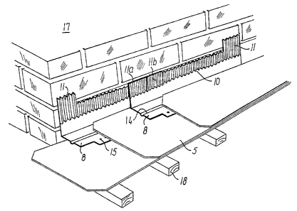
In the embodiment shown in Fig. 2, the flashing
member 7 is provided with two locking flaps 11 and
corresponding thereto, the profile wall 8 is provided
with two corner recesses 16. In this way the same
design of the flashing member 7 may be used on all
sides of a roof-penetrating building part which are not
perpendicular to the pitch of the roof, and a correct
overlapping in respect of water drainage is obtained
between neighbouring members as will be seen from Fig.
3, which shows the overlapping between two neighbouring
members 7 with locking flaps 11a and lib in bent
locking position for providing a side frame member for
CA 02327347 2006-03-20
6
mounting against one side of a roof-penetrating build-
ing part in the form of a chimney 17.
Furthermore, a longitudinal groove 14 may option-
ally be provided in the profile wall 8, in which groove
a sealing member for sealing against the underside of
the roofing may be placed, and the profile wall 8 may
further have pre-made nailholes 15 for use in securing
the flashing members to battens 18 in the subjacent
roof structure.