Language selection

Search

Patent 2335438 Summary

Third-party information liability

Some of the information on this Web page has been provided by external sources. The Government of Canada is not responsible for the accuracy, reliability or currency of the information supplied by external sources. Users wishing to rely upon this information should consult directly with the source of the information. Content provided by external sources is not subject to official languages, privacy and accessibility requirements.

Claims and Abstract availability

Any discrepancies in the text and image of the Claims and Abstract are due to differing posting times. Text of the Claims and Abstract are posted:

  • At the time the application is open to public inspection;
  • At the time of issue of the patent (grant).
(12) Patent Application: (11) CA 2335438
(54) English Title: METHOD AND DEVICE FOR IMAGING AND ANALYSIS OF BIOPOLYMER ARRAYS
(54) French Title: PROCEDES ET DISPOSITIF D'IMAGERIE ET D'ANALYSE DE JEUX ORDONNES D'ECHANTILLONS DE BIOPOLYMERES
Status: Dead
Bibliographic Data
(51) International Patent Classification (IPC):
  • G01N 21/77 (2006.01)
  • G01N 21/55 (2006.01)
  • G01N 21/64 (2006.01)
(72) Inventors :
  • KURG, ANTS (Estonia)
  • BERIK, JEVGENI (Estonia)
  • METSPALU, ANDRES (Estonia)
(73) Owners :
  • ASPER OU (Estonia)
(71) Applicants :
  • ASPER OU (Estonia)
(74) Agent: KIRBY EADES GALE BAKER
(74) Associate agent:
(45) Issued:
(86) PCT Filing Date: 2000-04-20
(87) Open to Public Inspection: 2000-10-26
Availability of licence: N/A
(25) Language of filing: English

Patent Cooperation Treaty (PCT): Yes
(86) PCT Filing Number: PCT/EE2000/000001
(87) International Publication Number: WO2000/063677
(85) National Entry: 2000-12-15

(30) Application Priority Data:
Application No. Country/Territory Date
P 199900072 Estonia 1999-04-21

Abstracts

English Abstract


Total internal reflection fluorescence is used for imaging biopolymer arrays.
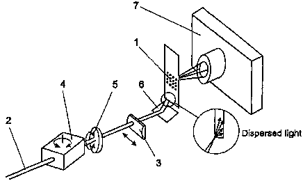
A beam of light (2) is guided into the solid support (1) at a certain angle,
evoking total internal reflection in the solid support. A certain portion of
light will not reflect from the inner glass surface but penetrate out of the
glass as an evanescent wave. It will excite fluorophores incorporated in the
biopolymer molecules, contiguously attached to the surface of the support.
Fluorescence thus evoked will be guided to a light sensitive element (7),
providing data on the fluorescent molecules attached to the surface of the
support. The said detection of fluorescence signals is rapid, taking about 10
seconds per fluorescence channel.


French Abstract

La fluorescence de la réflexion totale interne est utilisée pour l'imagerie de jeux ordonnés d'échantillons de biopolymères. Un faisceau de lumière (2) est dirigé à l'intérieur d'un support solide (1) à un certain angle, provoquant une réflexion totale interne dans le support solide. Une certaine partie de la lumière ne sera pas reflétée à partir de la surface de verre interne mais va sortir hors du verre sous la forme d'une onde évanescente. Elle va exciter les fluorophores incorporées dans les molécules de biopolymère, fixées de manière adjacente à la surface du support. La fluorescence ainsi provoquée va être dirigée vers un élément photosensible (7), fournissant des données concernant les molécules fluorescentes fixées à la surface du support. Ladite détection de signaux de fluorescence est rapide, parcourant en dix secondes environ chaque canal de fluorescence.

Claims

Note: Claims are shown in the official language in which they were submitted.


6
Claims
1. A method of imaging and analysis of a biopolymer array characterized in
that a
beam of light of certain wavelength is directed into the array support under
such an angle
that total internal reflection is evoked in the support, the support becomes a
waveguide and
part of the light penetrates out of the surface of the support as an
evanescent wave and
excites fluorophores incorporated in molecules immediately attached to the
surface.
2. A method according to claim 1, characterized in that the beam of light is a
laser
beam.
3. A fluorescence detector for applying the methods in claim 1 and 2
comprising a
digitally controlled CCD camera (7), band-pass filters and a scattering
cylindrical lens (3)
for broadening the zone of illumination.
4. A fluorescence detector according to claim 3, characterized in that the
broadening of the zone in the biopolymer array support is accomplished by a
scanning
movement of the laser beam, wherein the said scanning accomplished by a
transparent
hexahedron or slab (4), revolving of which changes the laser beam's angle of
entrance into
the support (1).
5. A fluorescence detector according to claim 3 or 4, characterized in that a
modulating element is used for a more even distribution of light in the
support (1).
6. A fluorescence detector according to claim 5, characterized in that the
modulating element is an optical wedge (5) revolving around its axis, wherein
the axis of
the optical wedge lies close to the optical axis of the laser beam.
7. A fluorescence detector according to any claim from 3 to 6, characterized
in that
the edge or side surface of entry of the laser beam into the support (1), is
frosted for
dispersion of light for a more even distribution of the laser beam in the
support.


7
8. A fluorescence detector according to any claim from 3 to 7, characterized
in that
the edge or side surface of entry of the laser beam into the support (1), is
polished for a
greater intensity of the laser beam in the support.
9. A fluorescence detector according to any claim from 3 to 8, characterized
in that
a diffraction grating applied on the support (1) is used to direct the laser
beam into the
support (1).
10. A fluorescence detector according to any claim from 3 to 9, characterized
in that
the laser beam is directed into the support (1) through its side surface using
the optical
prism (8).
11. A fluorescence detector according to any claim from 3 to 10, characterized
in
that between the support (1) and the prism (8) is placed a transparent liquid
(9), for
example, immersion oil, refractive index of which is close to those of the
prism (8) and the
support (1).

Description

Note: Descriptions are shown in the official language in which they were submitted.


CA 02335438 2000-12-15
WO 00/63677 PCT/EE00/00001
Method and device for imaging and analysis of biopolymer arrays
TECHNICAL FIELD
The present invention falls in the fields of molecular biology, molecular
diagnostics and
laser optics. It more specifically concerns a method of parallel detection and
analysis of
fluorescently labelled biopolymer molecules on a two-dimensional array, using
total
internal reflection fluorescence and a device for fluorescence detection.
BACKGROUND ART
On chemical binding of pre-fabricated short biopolymers (nucleic acids,
peptides etc) on a
solid transparent support (glass) in a two-dimensional structure, the said
array structure can
be used for diagnostic purposes, for example, when adding (hybridizing) a
sample target
nucleic acid to the array of bound nucleotide polymers. The target sample may
be labelled
with fluorophores prior to hybridization, but the incorporation of the label
may take place
immediately prior to scanning. For imaging and analyzing nucleic acid arrays,
apparatuses
based on different physical principles may be used, mainly falling in two
categories:
firstly, detectors and secondly, scanners based on confocaI microscopy.
The closest model to the device described in this invention, a fluorescence
detector based
on total internal reflection, is an instrument based on CCD camera called
GenoSensorTM,
manufactured by Vysis, Inc. (Downers Grove, IL,, USA).
The CCD camera-based instrument GenoSensor''M functions as follows. The
fluorescently
labelled target molecules, hybridized to DNA probes bound on a glass support,
are
detected following excitation by light traversing the DNA array (fig. 1). The
light is
generated by a xenon bulb and passed through a filter to select for the
necessary spectral
band. The light emitted by fluorophores will be filtered through an emission
filter and
guided through an optical system onto the high-resolution cooled CCD camera.
The signals
obtained will be processed in a computer.


CA 02335438 2000-12-15
WO 00/63677 PCT/EE00/00001
2
A nucleic acid array is a high-density, two-dimensional structure of nucleic
acid molecules
bound to a solid transparent support. Assessing the results of a biological
reaction made on
the array is problematic due to the low sensitivity and selectivity (using
traversing light for
excitation of fluorochromes is inefficient as_ a band for excitation has to be
filtered out of
the full spectrum) and the speed of detection (scanning is usually time-
consuming). As in
the case of arrayed primer extension reaction (APES, four different
dideoxynucleotides or
terminators, each carrying a different fluorophore, are used simultaneously in
the reaction,
a detector functioning in four spectral areas is needed for imaging the
nucleic acid array.
The said detector must be capable of maximal excitation and signal capture of
each
fluorophore, enabling an assembly of composite reaction result.
DISCLOSURE OF INVENTION
As a solution to the problems mentioned above, this invention suggests a
method
comprising total internal reflection fluorescence (fig. 2) for imaging
biopolymer arrays
(like determining sequences of target DNA) and a device of fluorescence
detector enabling
a quick and precise estimation of reaction results on a nucleic acid array in
four different
spectral bands.
The purpose of this invention is to provide a device and method for the
analysis of
biological reactions made on a biopolymer array or "chip". The arrays of
nucleic acids can
mainly be used in two ways. Firstly, in the case of assays based on
hybridization only, the
fluorescently labelled target to be analyzed will be hybridized to genetic
material
immobilized on the array. The label has been incorporated in the course of
amplification.
As the energy of hydrogen bonds formed between nitrogen bases in the double
strand
nucleic acid is limited, this type of hybridization-based reaction mechanism
is not
particularly selective and does not permit a clear distinction between signal
and noise.
Another possibility lies in the addition of an enzymatic reaction to the
hybridization of
immobilized oligonucleotide probes and the target nucleic acid. An example
would be
poiymerase-mediated extension, where every immobilized oligonucleotide becomes
elongated by one, fluorescently labelled nucleotide. The DNA polymerase adds a
nucleotide with respect to the genetic information of the target DNA.


CA 02335438 2000-12-15
WO 00/63677 PCT/EE00/00001
3
The arrayed DNA extension reaction uses as a substrate for DNA polymerase,
dideoxynucleotides labelled with fluorophores. Four differently labelled
dideoxynucleotides are used simultaneously, but only one will be incorporated
in a probe,
that corresponding to the primary structure of the target nucleic acid.
The said enzymatic mechanism possesses advantages over the reaction based
solely on
hybridization:
1. If the hybridization between the immobilized probe and the target is not
perfect, the
polymerase will neither recognize the structure nor carry out a reaction.
2. If the hybridization is perfect, the enzyme will incorporate a
dideoxynucleotide in the
probe, synthesizing a stable covalent bond. This enables a wash of the array
after the
reaction and getting rid of non-specifically bound biological material. Thus a
substantially
improved signaUnoise ratio will be achieved, enabling this system to detect
heterozygous
mutations.
The method described in this invention is used for analysis of biopolymer
arrays. A beam
of light of known wavelength (a laser beam) is directed into the edge of the
support (glass)
under an angle that will evoke total internal reflection of the beam. The
support becomes a
waveguide (fig. 2). A certain part of light will not reflect from the inner
surface of glass
but will penetrate out of the glass as an evanescent wave. Its intensity will
fall
exponentially but will remain sufficient for a distance of '/. of the
wavelength: This
distance is sufficient to excite the fluorophores incorporated in the probes
bound
ZS immediately to the glass. As in the case of polymerase extension there are
four different
nucleotides/labels, laser beams of four different wavelengths are used to
achieve maximal
excitation of fluorescent labels. The light emitted will be gathered through
respective
emission filters to discard the background light and focused through an
optical system
(objective) into a CCD camera. As the camera used is cooled, the imaging time
is short,
taking about 10 seconds for each nucleotide/fluorescence channel.


CA 02335438 2000-12-15
WO 00/63677 PCT/EE00/00001
4
BRIEF DESCRIPTION OF DRAWJTIGS
The invention is described with the help of figures, where:
fig. 1 is the excitation of fluorochromes on the surface of a biopolymer array
by a
traversing light;
fig. 2 is the said excitation by total internal reflection fluorescence
according to the method
in this invention;
fig. 3 is an application of the method in this invention where the laser beam
to evoke total
internal reflection is focused through a cylindrical lens thus that its
diameter is less than the
thickness of the support;
fig. 4 is an appiication of the method in this invention where a prism is used
to direct the
laser beam into the support. Between the prism and the support there is
transparent liquid,
refractive index of which is close to those of the prism and the support;
fig. 5 is the principal design of the device in this invention, the
fluorescence detector.
Figures 2 to 4 illustrate the method in this invention for imaging biopolymer
arrays. The
fluorescently labelled biopolymer molecules are bound to a thin transparent
support with
parallel walls ( 1 ). For maximal excitation of the fluorescent molecules a
laser beam (2) is
used. The beam is focused through a cylindrical lens (3) in a shape of a fan
thinner than the
edge ( 1 ), wherein the beam is directed into the edge ( 1 ) under such an
angle that the
support becomes a waveguide of total internal reflection.
The fluorescence obtained by laser beam is optically directed to a light-
sensitive element
which renders images of the fluorescent molecules bound on the support (1).
The
fluorescents obtained by previously prescribed mechanism is projected to the
light-
sensitive element, which enables to obtain to the support ( 1 ) the images of
the bound and
excited by laser beam fluorescent molecules as shown in the fig. 5. The laser
beam is
directed to the support through the side surface. A digitally controlled CCD
camera is used


CA 02335438 2000-12-15
WO 00/63677 PCT/EE00/00001
S
as the light-sensitive element. The laser beam is scattered through a
transparent slab or
hexahedron (4) and modulated in the same time with an optical wedge (5). These
elements
combined modify the angle of the laser beam coming from the mirror (6) into
the support
(1).
To direct the beam into the support (1) trough the edge surface the prism (8)
is used as
shown in the fig. 4. To reduce the reflection loss in transitions of the light
from the prism
(8) to support (1) is used the transparent liquid (9), for example the
immersion oil used in
the microscopy, which refractive index is close to the refractive index of the
prism (8) and
the support ( 1 ).
Though the invention is prescribed in connection with the practical preferred
embodiment
it is understandable, that the invention is not limited with the prescribed
subject matter but
in opposite, the invention is intended to include different modification and
equivalent
devices which comprises in the idea and scope of the added patent claim.

Representative Drawing
A single figure which represents the drawing illustrating the invention.
Administrative Status

For a clearer understanding of the status of the application/patent presented on this page, the site Disclaimer , as well as the definitions for Patent , Administrative Status , Maintenance Fee  and Payment History  should be consulted.

Administrative Status

Title Date
Forecasted Issue Date Unavailable
(86) PCT Filing Date 2000-04-20
(87) PCT Publication Date 2000-10-26
(85) National Entry 2000-12-15
Dead Application 2004-04-20

Abandonment History

Abandonment Date Reason Reinstatement Date
2003-04-22 FAILURE TO PAY APPLICATION MAINTENANCE FEE

Payment History

Fee Type Anniversary Year Due Date Amount Paid Paid Date
Registration of a document - section 124 $100.00 2000-12-15
Application Fee $300.00 2000-12-15
Maintenance Fee - Application - New Act 2 2002-04-22 $100.00 2002-04-22
Owners on Record

Note: Records showing the ownership history in alphabetical order.

Current Owners on Record
ASPER OU
Past Owners on Record
BERIK, JEVGENI
KURG, ANTS
METSPALU, ANDRES
Past Owners that do not appear in the "Owners on Record" listing will appear in other documentation within the application.
Documents

To view selected files, please enter reCAPTCHA code :


To view images, click a link in the Document Description column. To download the documents, select one or more checkboxes in the first column and then click the "Download Selected in PDF format (Zip Archive)" or the "Download Selected as Single PDF" button.

List of published and non-published patent-specific documents on the CPD .

If you have any difficulty accessing content, you can call the Client Service Centre at 1-866-997-1936 or send them an e-mail at CIPO Client Service Centre.


Document
Description 
Date
(yyyy-mm-dd) 
Number of pages   Size of Image (KB) 
Cover Page 2001-04-05 1 51
Representative Drawing 2001-04-05 1 8
Abstract 2000-12-15 1 59
Description 2000-12-15 5 236
Claims 2000-12-15 2 67
Drawings 2000-12-15 2 30
Correspondence 2001-03-14 1 24
Assignment 2000-12-15 4 126
PCT 2000-12-15 4 139
Correspondence 2001-05-15 1 35
Assignment 2001-10-24 7 180