Sélection de la langue

Search

Sommaire du brevet 2335438 

Énoncé de désistement de responsabilité concernant l'information provenant de tiers

Une partie des informations de ce site Web a été fournie par des sources externes. Le gouvernement du Canada n'assume aucune responsabilité concernant la précision, l'actualité ou la fiabilité des informations fournies par les sources externes. Les utilisateurs qui désirent employer cette information devraient consulter directement la source des informations. Le contenu fourni par les sources externes n'est pas assujetti aux exigences sur les langues officielles, la protection des renseignements personnels et l'accessibilité.

Disponibilité de l'Abrégé et des Revendications

L'apparition de différences dans le texte et l'image des Revendications et de l'Abrégé dépend du moment auquel le document est publié. Les textes des Revendications et de l'Abrégé sont affichés :

  • lorsque la demande peut être examinée par le public;
  • lorsque le brevet est émis (délivrance).
(12) Demande de brevet: (11) CA 2335438
(54) Titre français: PROCEDES ET DISPOSITIF D'IMAGERIE ET D'ANALYSE DE JEUX ORDONNES D'ECHANTILLONS DE BIOPOLYMERES
(54) Titre anglais: METHOD AND DEVICE FOR IMAGING AND ANALYSIS OF BIOPOLYMER ARRAYS
Statut: Réputée abandonnée et au-delà du délai pour le rétablissement - en attente de la réponse à l’avis de communication rejetée
Données bibliographiques
(51) Classification internationale des brevets (CIB):
  • G01N 21/77 (2006.01)
  • G01N 21/64 (2006.01)
(72) Inventeurs :
  • METSPALU, ANDRES (Estonie)
  • BERIK, JEVGENI (Estonie)
  • KURG, ANTS (Estonie)
(73) Titulaires :
  • ASPER OU
(71) Demandeurs :
  • ASPER OU (Estonie)
(74) Agent: KIRBY EADES GALE BAKER
(74) Co-agent:
(45) Délivré:
(86) Date de dépôt PCT: 2000-04-20
(87) Mise à la disponibilité du public: 2000-10-26
Licence disponible: S.O.
Cédé au domaine public: S.O.
(25) Langue des documents déposés: Anglais

Traité de coopération en matière de brevets (PCT): Oui
(86) Numéro de la demande PCT: PCT/EE2000/000001
(87) Numéro de publication internationale PCT: EE2000000001
(85) Entrée nationale: 2000-12-15

(30) Données de priorité de la demande:
Numéro de la demande Pays / territoire Date
P 199900072 (Estonie) 1999-04-21

Abrégés

Abrégé français

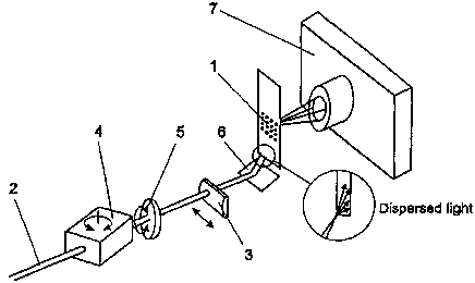
La fluorescence de la réflexion totale interne est utilisée pour l'imagerie de jeux ordonnés d'échantillons de biopolymères. Un faisceau de lumière (2) est dirigé à l'intérieur d'un support solide (1) à un certain angle, provoquant une réflexion totale interne dans le support solide. Une certaine partie de la lumière ne sera pas reflétée à partir de la surface de verre interne mais va sortir hors du verre sous la forme d'une onde évanescente. Elle va exciter les fluorophores incorporées dans les molécules de biopolymère, fixées de manière adjacente à la surface du support. La fluorescence ainsi provoquée va être dirigée vers un élément photosensible (7), fournissant des données concernant les molécules fluorescentes fixées à la surface du support. Ladite détection de signaux de fluorescence est rapide, parcourant en dix secondes environ chaque canal de fluorescence.


Abrégé anglais


Total internal reflection fluorescence is used for imaging biopolymer arrays.
A beam of light (2) is guided into the solid support (1) at a certain angle,
evoking total internal reflection in the solid support. A certain portion of
light will not reflect from the inner glass surface but penetrate out of the
glass as an evanescent wave. It will excite fluorophores incorporated in the
biopolymer molecules, contiguously attached to the surface of the support.
Fluorescence thus evoked will be guided to a light sensitive element (7),
providing data on the fluorescent molecules attached to the surface of the
support. The said detection of fluorescence signals is rapid, taking about 10
seconds per fluorescence channel.

Revendications

Note : Les revendications sont présentées dans la langue officielle dans laquelle elles ont été soumises.


6
Claims
1. A method of imaging and analysis of a biopolymer array characterized in
that a
beam of light of certain wavelength is directed into the array support under
such an angle
that total internal reflection is evoked in the support, the support becomes a
waveguide and
part of the light penetrates out of the surface of the support as an
evanescent wave and
excites fluorophores incorporated in molecules immediately attached to the
surface.
2. A method according to claim 1, characterized in that the beam of light is a
laser
beam.
3. A fluorescence detector for applying the methods in claim 1 and 2
comprising a
digitally controlled CCD camera (7), band-pass filters and a scattering
cylindrical lens (3)
for broadening the zone of illumination.
4. A fluorescence detector according to claim 3, characterized in that the
broadening of the zone in the biopolymer array support is accomplished by a
scanning
movement of the laser beam, wherein the said scanning accomplished by a
transparent
hexahedron or slab (4), revolving of which changes the laser beam's angle of
entrance into
the support (1).
5. A fluorescence detector according to claim 3 or 4, characterized in that a
modulating element is used for a more even distribution of light in the
support (1).
6. A fluorescence detector according to claim 5, characterized in that the
modulating element is an optical wedge (5) revolving around its axis, wherein
the axis of
the optical wedge lies close to the optical axis of the laser beam.
7. A fluorescence detector according to any claim from 3 to 6, characterized
in that
the edge or side surface of entry of the laser beam into the support (1), is
frosted for
dispersion of light for a more even distribution of the laser beam in the
support.

7
8. A fluorescence detector according to any claim from 3 to 7, characterized
in that
the edge or side surface of entry of the laser beam into the support (1), is
polished for a
greater intensity of the laser beam in the support.
9. A fluorescence detector according to any claim from 3 to 8, characterized
in that
a diffraction grating applied on the support (1) is used to direct the laser
beam into the
support (1).
10. A fluorescence detector according to any claim from 3 to 9, characterized
in that
the laser beam is directed into the support (1) through its side surface using
the optical
prism (8).
11. A fluorescence detector according to any claim from 3 to 10, characterized
in
that between the support (1) and the prism (8) is placed a transparent liquid
(9), for
example, immersion oil, refractive index of which is close to those of the
prism (8) and the
support (1).

Description

Note : Les descriptions sont présentées dans la langue officielle dans laquelle elles ont été soumises.


CA 02335438 2000-12-15
WO 00/63677 PCT/EE00/00001
Method and device for imaging and analysis of biopolymer arrays
TECHNICAL FIELD
The present invention falls in the fields of molecular biology, molecular
diagnostics and
laser optics. It more specifically concerns a method of parallel detection and
analysis of
fluorescently labelled biopolymer molecules on a two-dimensional array, using
total
internal reflection fluorescence and a device for fluorescence detection.
BACKGROUND ART
On chemical binding of pre-fabricated short biopolymers (nucleic acids,
peptides etc) on a
solid transparent support (glass) in a two-dimensional structure, the said
array structure can
be used for diagnostic purposes, for example, when adding (hybridizing) a
sample target
nucleic acid to the array of bound nucleotide polymers. The target sample may
be labelled
with fluorophores prior to hybridization, but the incorporation of the label
may take place
immediately prior to scanning. For imaging and analyzing nucleic acid arrays,
apparatuses
based on different physical principles may be used, mainly falling in two
categories:
firstly, detectors and secondly, scanners based on confocaI microscopy.
The closest model to the device described in this invention, a fluorescence
detector based
on total internal reflection, is an instrument based on CCD camera called
GenoSensorTM,
manufactured by Vysis, Inc. (Downers Grove, IL,, USA).
The CCD camera-based instrument GenoSensor''M functions as follows. The
fluorescently
labelled target molecules, hybridized to DNA probes bound on a glass support,
are
detected following excitation by light traversing the DNA array (fig. 1). The
light is
generated by a xenon bulb and passed through a filter to select for the
necessary spectral
band. The light emitted by fluorophores will be filtered through an emission
filter and
guided through an optical system onto the high-resolution cooled CCD camera.
The signals
obtained will be processed in a computer.

CA 02335438 2000-12-15
WO 00/63677 PCT/EE00/00001
2
A nucleic acid array is a high-density, two-dimensional structure of nucleic
acid molecules
bound to a solid transparent support. Assessing the results of a biological
reaction made on
the array is problematic due to the low sensitivity and selectivity (using
traversing light for
excitation of fluorochromes is inefficient as_ a band for excitation has to be
filtered out of
the full spectrum) and the speed of detection (scanning is usually time-
consuming). As in
the case of arrayed primer extension reaction (APES, four different
dideoxynucleotides or
terminators, each carrying a different fluorophore, are used simultaneously in
the reaction,
a detector functioning in four spectral areas is needed for imaging the
nucleic acid array.
The said detector must be capable of maximal excitation and signal capture of
each
fluorophore, enabling an assembly of composite reaction result.
DISCLOSURE OF INVENTION
As a solution to the problems mentioned above, this invention suggests a
method
comprising total internal reflection fluorescence (fig. 2) for imaging
biopolymer arrays
(like determining sequences of target DNA) and a device of fluorescence
detector enabling
a quick and precise estimation of reaction results on a nucleic acid array in
four different
spectral bands.
The purpose of this invention is to provide a device and method for the
analysis of
biological reactions made on a biopolymer array or "chip". The arrays of
nucleic acids can
mainly be used in two ways. Firstly, in the case of assays based on
hybridization only, the
fluorescently labelled target to be analyzed will be hybridized to genetic
material
immobilized on the array. The label has been incorporated in the course of
amplification.
As the energy of hydrogen bonds formed between nitrogen bases in the double
strand
nucleic acid is limited, this type of hybridization-based reaction mechanism
is not
particularly selective and does not permit a clear distinction between signal
and noise.
Another possibility lies in the addition of an enzymatic reaction to the
hybridization of
immobilized oligonucleotide probes and the target nucleic acid. An example
would be
poiymerase-mediated extension, where every immobilized oligonucleotide becomes
elongated by one, fluorescently labelled nucleotide. The DNA polymerase adds a
nucleotide with respect to the genetic information of the target DNA.

CA 02335438 2000-12-15
WO 00/63677 PCT/EE00/00001
3
The arrayed DNA extension reaction uses as a substrate for DNA polymerase,
dideoxynucleotides labelled with fluorophores. Four differently labelled
dideoxynucleotides are used simultaneously, but only one will be incorporated
in a probe,
that corresponding to the primary structure of the target nucleic acid.
The said enzymatic mechanism possesses advantages over the reaction based
solely on
hybridization:
1. If the hybridization between the immobilized probe and the target is not
perfect, the
polymerase will neither recognize the structure nor carry out a reaction.
2. If the hybridization is perfect, the enzyme will incorporate a
dideoxynucleotide in the
probe, synthesizing a stable covalent bond. This enables a wash of the array
after the
reaction and getting rid of non-specifically bound biological material. Thus a
substantially
improved signaUnoise ratio will be achieved, enabling this system to detect
heterozygous
mutations.
The method described in this invention is used for analysis of biopolymer
arrays. A beam
of light of known wavelength (a laser beam) is directed into the edge of the
support (glass)
under an angle that will evoke total internal reflection of the beam. The
support becomes a
waveguide (fig. 2). A certain part of light will not reflect from the inner
surface of glass
but will penetrate out of the glass as an evanescent wave. Its intensity will
fall
exponentially but will remain sufficient for a distance of '/. of the
wavelength: This
distance is sufficient to excite the fluorophores incorporated in the probes
bound
ZS immediately to the glass. As in the case of polymerase extension there are
four different
nucleotides/labels, laser beams of four different wavelengths are used to
achieve maximal
excitation of fluorescent labels. The light emitted will be gathered through
respective
emission filters to discard the background light and focused through an
optical system
(objective) into a CCD camera. As the camera used is cooled, the imaging time
is short,
taking about 10 seconds for each nucleotide/fluorescence channel.

CA 02335438 2000-12-15
WO 00/63677 PCT/EE00/00001
4
BRIEF DESCRIPTION OF DRAWJTIGS
The invention is described with the help of figures, where:
fig. 1 is the excitation of fluorochromes on the surface of a biopolymer array
by a
traversing light;
fig. 2 is the said excitation by total internal reflection fluorescence
according to the method
in this invention;
fig. 3 is an application of the method in this invention where the laser beam
to evoke total
internal reflection is focused through a cylindrical lens thus that its
diameter is less than the
thickness of the support;
fig. 4 is an appiication of the method in this invention where a prism is used
to direct the
laser beam into the support. Between the prism and the support there is
transparent liquid,
refractive index of which is close to those of the prism and the support;
fig. 5 is the principal design of the device in this invention, the
fluorescence detector.
Figures 2 to 4 illustrate the method in this invention for imaging biopolymer
arrays. The
fluorescently labelled biopolymer molecules are bound to a thin transparent
support with
parallel walls ( 1 ). For maximal excitation of the fluorescent molecules a
laser beam (2) is
used. The beam is focused through a cylindrical lens (3) in a shape of a fan
thinner than the
edge ( 1 ), wherein the beam is directed into the edge ( 1 ) under such an
angle that the
support becomes a waveguide of total internal reflection.
The fluorescence obtained by laser beam is optically directed to a light-
sensitive element
which renders images of the fluorescent molecules bound on the support (1).
The
fluorescents obtained by previously prescribed mechanism is projected to the
light-
sensitive element, which enables to obtain to the support ( 1 ) the images of
the bound and
excited by laser beam fluorescent molecules as shown in the fig. 5. The laser
beam is
directed to the support through the side surface. A digitally controlled CCD
camera is used

CA 02335438 2000-12-15
WO 00/63677 PCT/EE00/00001
S
as the light-sensitive element. The laser beam is scattered through a
transparent slab or
hexahedron (4) and modulated in the same time with an optical wedge (5). These
elements
combined modify the angle of the laser beam coming from the mirror (6) into
the support
(1).
To direct the beam into the support (1) trough the edge surface the prism (8)
is used as
shown in the fig. 4. To reduce the reflection loss in transitions of the light
from the prism
(8) to support (1) is used the transparent liquid (9), for example the
immersion oil used in
the microscopy, which refractive index is close to the refractive index of the
prism (8) and
the support ( 1 ).
Though the invention is prescribed in connection with the practical preferred
embodiment
it is understandable, that the invention is not limited with the prescribed
subject matter but
in opposite, the invention is intended to include different modification and
equivalent
devices which comprises in the idea and scope of the added patent claim.

Dessin représentatif
Une figure unique qui représente un dessin illustrant l'invention.
États administratifs

2024-08-01 : Dans le cadre de la transition vers les Brevets de nouvelle génération (BNG), la base de données sur les brevets canadiens (BDBC) contient désormais un Historique d'événement plus détaillé, qui reproduit le Journal des événements de notre nouvelle solution interne.

Veuillez noter que les événements débutant par « Inactive : » se réfèrent à des événements qui ne sont plus utilisés dans notre nouvelle solution interne.

Pour une meilleure compréhension de l'état de la demande ou brevet qui figure sur cette page, la rubrique Mise en garde , et les descriptions de Brevet , Historique d'événement , Taxes périodiques et Historique des paiements devraient être consultées.

Historique d'événement

Description Date
Inactive : CIB expirée 2014-01-01
Inactive : CIB de MCD 2006-03-12
Demande non rétablie avant l'échéance 2004-04-20
Le délai pour l'annulation est expiré 2004-04-20
Réputée abandonnée - omission de répondre à un avis sur les taxes pour le maintien en état 2003-04-22
Inactive : Grandeur de l'entité changée 2002-05-06
Lettre envoyée 2001-11-21
Inactive : Transfert individuel 2001-10-24
Inactive : Grandeur de l'entité changée 2001-05-24
Inactive : Page couverture publiée 2001-04-05
Inactive : CIB enlevée 2001-03-26
Inactive : CIB en 1re position 2001-03-26
Inactive : CIB en 1re position 2001-03-25
Inactive : Lettre de courtoisie - Preuve 2001-03-20
Inactive : Notice - Entrée phase nat. - Pas de RE 2001-03-14
Demande reçue - PCT 2001-03-13
Demande publiée (accessible au public) 2000-10-26

Historique d'abandonnement

Date d'abandonnement Raison Date de rétablissement
2003-04-22

Taxes périodiques

Le dernier paiement a été reçu le 2002-04-22

Avis : Si le paiement en totalité n'a pas été reçu au plus tard à la date indiquée, une taxe supplémentaire peut être imposée, soit une des taxes suivantes :

  • taxe de rétablissement ;
  • taxe pour paiement en souffrance ; ou
  • taxe additionnelle pour le renversement d'une péremption réputée.

Les taxes sur les brevets sont ajustées au 1er janvier de chaque année. Les montants ci-dessus sont les montants actuels s'ils sont reçus au plus tard le 31 décembre de l'année en cours.
Veuillez vous référer à la page web des taxes sur les brevets de l'OPIC pour voir tous les montants actuels des taxes.

Historique des taxes

Type de taxes Anniversaire Échéance Date payée
Taxe nationale de base - générale 2000-12-15
Enregistrement d'un document 2000-12-15
TM (demande, 2e anniv.) - générale 02 2002-04-22 2002-04-22
Titulaires au dossier

Les titulaires actuels et antérieures au dossier sont affichés en ordre alphabétique.

Titulaires actuels au dossier
ASPER OU
Titulaires antérieures au dossier
ANDRES METSPALU
ANTS KURG
JEVGENI BERIK
Les propriétaires antérieurs qui ne figurent pas dans la liste des « Propriétaires au dossier » apparaîtront dans d'autres documents au dossier.
Documents

Pour visionner les fichiers sélectionnés, entrer le code reCAPTCHA :


Pour visualiser une image, cliquer sur un lien dans la colonne description du document. Pour télécharger l'image (les images), cliquer l'une ou plusieurs cases à cocher dans la première colonne et ensuite cliquer sur le bouton "Télécharger sélection en format PDF (archive Zip)" ou le bouton "Télécharger sélection (en un fichier PDF fusionné)".

Liste des documents de brevet publiés et non publiés sur la BDBC .

Si vous avez des difficultés à accéder au contenu, veuillez communiquer avec le Centre de services à la clientèle au 1-866-997-1936, ou envoyer un courriel au Centre de service à la clientèle de l'OPIC.


Description du
Document 
Date
(aaaa-mm-jj) 
Nombre de pages   Taille de l'image (Ko) 
Dessin représentatif 2001-04-04 1 8
Abrégé 2000-12-14 1 58
Description 2000-12-14 5 236
Revendications 2000-12-14 2 67
Dessins 2000-12-14 2 30
Avis d'entree dans la phase nationale 2001-03-13 1 194
Courtoisie - Certificat d'enregistrement (document(s) connexe(s)) 2001-11-20 1 113
Rappel de taxe de maintien due 2001-12-23 1 111
Courtoisie - Lettre d'abandon (taxe de maintien en état) 2003-05-19 1 176
Correspondance 2001-03-13 1 24
PCT 2000-12-14 4 140
Correspondance 2001-05-14 1 35