Note: Descriptions are shown in the official language in which they were submitted.
CA 02361224 2001-11-07
-1-
TITLE OF THE INVENTION
Air drag reducing apparatus.
FIELD OF THE INVENTION
The present invention relates to an air drag reducing apparatus for use with
vehicles having a rectangular rear end closed by a pair of hingedly mounted
doors.
BACKGROUND OF THE INVENTION
It is known that a significant amount of air drag results when a vehicle
travels
over a roadway; this is due to an area of low pressure created at the rear end
of
the vehicle. For example, with a tractor-trailer type vehicle, the air makes a
sharp
bend around the squared-off back of the trailer, thus causing turbulence and
drag. To overcome this problem, engine power is required and therefore fuel.
Furthermore, the turbulence also causes poor visibility in rainy conditions
and an
accumulation of dirt on the back of trailers.
In the trucking industry, the aerodynamics of vehicles is a growing concern.
Tests indicate that fuel savings from aerodynamic improvements are equivalent
to fuel savings attained by a chassis weight reduction and require fewer
services
to maintain. The air resistance or aerodynamic drag of the vehicle increases
the
power needed by the engine as the speed increases. It is known that a tractor-
trailer needs about 100 HP to overtake the air drag at a speed of 55 MPH.
Approximately half the energy reaching the drive wheels is required to
overcome
air resistance at cruising speed. Recent tests reveal that the square back end
contributes approximately to 30% of the air drag. Therefore, the addition of
aerodynamic device, such as a rear defector, diminishes the air drag and
results
in lower fuel consumption.
Various devices have been proposed to reduce air drag.
CA 02361224 2001-11-07
-2-
One air drag reducing apparatus may be found described in U.S. patent No.
4,214,787 issued July 29, 1980 to Chain wherein a pair of trim panels are
pivotally connected to the rear end of the vehicle with control means
connected
between each trim panel and the rear end of the vehicle for maintaining the
trim
panel in an upward position when the vehicle is moving at a rate exceeding a
pre-
determined minimum velocity. The drag reducing apparatus described in this
patent includes a control assembly, which automatically controls the movement
of the trim panels between an operating position and a storage position
adjacent
the vehicle doors. The control system comprises a panel actuator in the form
of
a ram, which is responsible to the application of pressurized fluid or air by
the
operator of the vehicle to maintain the panel in the drag reducing position.
However, in this drag apparatus, the ram construction does not enable the
doors
to be moved between a closed position to a completely opened position where
the doors are adjacently parallel to the sides of the trailer vehicle.
Another air drag reducing apparatus may be found in applicant's Canadian
patent
application serial number 2,316,584 published February 24, 2001.
OBJECTS AND STATEMENT OF THE INVENTION
The present invention is concerned with providing an air drag reducing
apparatus
which overcomes the above-described problems.
More specifically, this is achieved by providing an apparatus which allows the
panels to be moved outwardly from a drag reducing position to a position where
the doors are in their fully retracted position adjacent their associated
sides of the
vehicle.
A further object of the present invention is to provide a mechanism which will
enable the panels to return back to their drag reducing position whenever the
doors are hingedly moved from their retracted position to their end closing
position. This is achieved by providing a pressure exerting element which
assists
the panel to return to its drag reducing position.
CA 02361224 2001-11-07
-3-
The present invention therefore relates to an air drag reducing apparatus for
use
with a vehicle having a top and opposite lateral sides contiguous with a rear
end
formed of a pair of hingedly mounted rectangular doors movable between a
closed position to a fully open retracted position wherein the doors panels
are
respectively retracted adjacent to a corresponding side of the vehicle; the
apparatus comprising:
a pair of elongated generally rectangular side panels each having
opposite short sides and opposite long sides, the long sides defining a
leading
edge and a trailing edge;
hinge means connecting each side panel allowing for pivotal
movement relative to a corresponding door of the vehicle;
means associated with each side panel for maintaining the side
panel in a drag reducing position rearwardly of a corresponding closed door
wherein the side panel defines an angle of about 16° with a rearward
projection
of a plane of the corresponding side of the vehicle;
a pair of generally rectangular top panels each having opposite
short sides and opposite long sides, the long sides defining a leading edge
and
a trailing edge; the short sides of the top panels including one short side
disposed adjacent an inner face of a corresponding one of the side panels when
the side panels are in the drag reducing position; and
means associated with the top panels for maintaining the top panels in
a drag reducing position rearwardly of a corresponding closed door wherein
each
top panel defines an angle of about 16° with a rearward projection of a
plane of
the top of the vehicle; the maintaining means associated with the top panels
allowing the top panels to be moved from the drag reducing position to a
position
lying substantially parallel to a corresponding side of the vehicle between a
corresponding side panel and a corresponding door in the fully open position.
In one preferred form of the invention, one short side of the top panels
includes
means that slidably contact the inner face of the side panels as the vehicle
doors
are opened.
CA 02361224 2001-11-07
-4-
In another form of the invention, the positioning means consist of gas
cylinders
connected between the door and the top panel.
Other objects and further scope of applicability of the present invention will
become apparent from the detailed description given hereinafter. It should be
understood, however, that this detailed description, while indicating
preferred
embodiments of the invention, is given by way of illustration only, since
various
changes and modifications within the spirit and scope of the invention will
become apparent to those skilled in the art.
BRIEF DESCRIPTION OF THE DRAWINGS
Figure 1 is a perspective view showing the rear of a vehicle equipped with a
series of air drag apparatuses made in accordance with the present invention;
Figure 1 a is an enlarged perspective view of the hinge arrangement of the
trailer
door and side panel;
Figure 2 is an elevational rear view of the vehicle and its panels;
Figure 3 is an elevational side view of the rear of the vehicle showing one
side
panel and one top panel;
Figure 4 is a top plan view of the rear of the vehicle and its panels;
Figure 5 is an elevational side view of the rear of the vehicle with one side
panel
removed for clarity purposes;
Figure 5a is an enlarged perspective view of a cylinder arrangement used with
the top panels of the invention;
Figure 6 is a top plan view showing a door with one side and one top panel in
the
opened position;
CA 02361224 2001-11-07
-5-
Figures 7 and 8 are top plan views showing various positions of the two doors
and their top and side panels in a door returning motion; and
Figure 9 is an elevational view of a variant of a side panel of the present
invention.
DESCRIPTION OF PREFERRED EMBODIMENTS
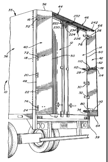
Referring to figure 1, there is shown the rear end of a vehicle 10, such as a
truck
or a trailer, which is closed by a pair of doors 12 and 14 of rectangular
shape.
The doors are respectively mounted by means of hinges 16, 18, 20, 22, 24 on
one side and 26, 28, 30, 32 and 34 on the other side so as to move from their
shown closed position to a fully retracted position where they are disposed
parallel and adjacent to the opposite sides 36 and 38 of the vehicle.
The present invention is concerned with providing, at the rear of vehicle, an
air
drag reducing apparatus which in the present case includes a pair of side
panels
40 and 42 and a pair of top panels 44 and 46. Panel 40 has a generally
elongated rectangular shape with a leading edge 48 and a trailing edge 50
(defining the long sides of the rectangle) and a pair of opposite sides 52 and
56
(defining the short sides of the rectangle). Similarly, the side panel 42 has
a
leading edge 60 and a trailing edge 62 defining the long sides of the
generally
rectangular panel and opposite short sides 64 and 66 representing the short
sides of the panel. These panels are preferably made of metal, such as
aluminum; however, other material, such as plastic or fiberglass, may be used.
Also, the width of these panels is preferably of about twenty inches or more.
Each panel 40, 42 is pivotally mounted at the corner of the vehicle by means
of
a series of hinges mounted to the pivot pins of the door hinges. Figure 1
shows
three hinges 76, 78, 80 fixed to the inner face of panel 42 and pivotally
mounted
on the door hinges 26, 28, 34 respectively. Figure 1 a shows in greater detail
that
hinge 78 is connected to pin 73 mounted to a C-shaped bracket 81 which is
CA 02361224 2001-11-07
-6-
fixedly secured to the rear frame 39 of the side 38 of the trailer. Hinge 28
is also
mounted to the pin 73 to allow for the pivotal movement of the door 14. A
spacer
79 is provided between the hinge 78 and the panel 42.
One or more cables 110 are provided to retain the side panels 40 and 42 in
their
16° angle; for example, referring to figures 1 and 1 a, these cables
110 have one
end 112 mounted to the hinge 28 and the opposite end 114 mounted to the
trailing edge 62 of the side panel 42.
As explained further below, panels 40 and 42 are positioned in a preferred
drag
reducing position rearwardly of a corresponding closed panel at an angle of
preferably about 16° with the rearward projection of the plane of the
corresponding side of the vehicle; figure 3 shows this angle with respect to
the
top side 35 of the vehicle while figure 4 shows this angle with respect to the
lateral side 36 of the vehicle.
With reference to figures 2 and 4, the top panel 44 has a generally
rectangular
shape with a leading edge 200 and a trailing edge 202 forming the long sides
of
the panel and a pair of short sides 204 and 206. Similarly, panel 46 has a
rectangular shape with a leading edge 210 and a trailing edge 212 forming the
long sides of the panel and a pair of opposite short sides 214 and 216.
Referring also to figure 1, these panels 44 and 46 are each pivotally mounted
to
their respective doors 12 and 14 by means of a pair of hinges 220 and 222 (for
panel 44) and 224 and 226 (for panel 46).
The air drag reducing apparatus of this embodiment of the present invention
includes of a pair of gas (inert or air) cylinders 228 and 230 for panel 44
and a
pair of gas (inert or air) cylinders 232 and 234 for panel 46. Referring to
figures
5 and 5a, one of the cylinder arrangements is shown in greater detail; it
consists
of a hinge 222 formed of two arms 222a and 222b respectively mounted to the
trailer door 12 and the top panel 44 and pivotable about pin 223. The cylinder
230 is pivotally connected, at each extremity, to the arms 222a and 222b. When
CA 02361224 2001-11-07
-7-
arm 222b is moved towards arm 222a, the cylinder is compressed. The
decompression of the cylinder returns the arms to their original position. In
the
air drag reducing position illustrated in figure 1, all gas cylinders are in
their
extended positions to maintain the top panels in the preferred air drag
reducing
angle of about 16° (see figure 3). In their air drag reducing
positions, the top
panels are contained between the upper part of the side panels so that these
top
panels prevent the side panels to further move inwardly towards the central
axis
of the vehicle. The outer extremity of each top panel includes a sliding
element,
such as roller 240, 242, which is adapted to contact the inner face of the
side
panels.
As the vehicle doors 12 and 14 are opened, the top panels swing outwardly with
their respective door, the rollers 240 and 242 contacting the inner face of
their
corresponding side panels which pivot outwardly about their respective hinges.
When the side panels reach contact with their corresponding side of the
vehicle,
the continuing pivotal movement of the vehicle doors cause the rollers 240 and
242 to roll downward along the side panels while simultaneously causing the
compressing of the gas cylinders 228, 230, 232 and 234 until the top panels
lie
vertically between the side panels (contacting the vehicle side) and the door
in
its fully retracted position lying substantially parallel to the vehicle side.
Although
not shown, securing means are provided on the doors to enable the doors to be
secured in their fully retracted position. Once these securing means are
released, the pressure in the cylinders forces the doors back to their closed
position, simultaneously raising the top panels to their drag reducing
position
where the cylinders reach their fully extended condition. This force exerted
by
the cylinders also reduces the manual pressure exerted by the operator in
returning the doors to their closed position.
Although the invention has been described with respect to two forms of
the invention, it will be evident to the person skilled in the art that it may
be
modified and refined in various ways. For example, referring to figure 9, the
side
panel 40' may be provided with a flexible member 300 made of rubber or like
material along its leading edge. This member 300 serves to protect the leading
CA 02361224 2001-11-07
edge when the door and side panel are moved to the outwardly fully retracted
position where it is subject to damage as the trailer is moved rearwardly and
impact on a solid wall as the like. It is therefore wished to have it
understood that
the present invention should not be limited in scope, except by the terms of
the
following claims.