Note: Descriptions are shown in the official language in which they were submitted.
CA 02364809 2001-12-11
- 1 -
ILLUMINATION LAMP EQUIPMENT
BACKGROUND OF THE INVENTION
1. Field of the Invention
The present invention relates to an improvement of
illumination lamp equipment to be mounted on the vehicle
illumination such as the interior lighting of the window
control switch, the interior lighting of the ashtray, and
the foot lighting, or on the front panel of the electronic
equipment, comprising a LED, a small light bulb, or the like
for indicating the operating position or the driving
condition.
2. Description of the Related Art
The conventional lighting tool used for illumination
lamp equipment described above includes LEDs or small light
bulbs. The exposed portion of the LED or the small light
bulb is made of glass or synthetic resin. Therefore, it is
difficult to mount these illumination lamps on the vehicle
or on the electronic equipment in the exposed state and it
may be broken very easily in the exposed state.
Therefore, in general, a housing for mounting the
illumination lamp such as the LED or the small light bulb is
manufactured and the illumination lamp is fitted into the
housing. However, since the housing is constructed of two
CA 02364809 2001-12-11
- 2 -
halves or formed into cylindrical shape, it is necessary to
combine two halves and secure with an adhesive agent with
the illumination lamp mounted, or to close the lid with the
illumination lamp mounted. Therefore, there is a problem in
that the point of fixation between the housing and the
illuminating lamp is susceptible to generation of a gap,
which may result in entering of dust or backlash, in
addition to the problem in that the number of components or
the number of manufacturing steps increases.
As a consequent, as a measure to solve the conventional
problems described above, molding the illumination lamp with
a nylon base synthetic resin, which is normally used for
molding, is conceivable. However, in the method of molding
the illumination lamp with nylon base resin, the temperature
of the resin is in the range of 240 to 300 C and the
injection pressure is in the range of 400 to 1300Kg/cm2 at
the time of injection as shown in Fig. 5, and thus the
illumination lamp such as the LED or the small light bulb
may be melt disadvantageously by the temperature of the
resin or may be broken by the injection pressure.
SUMMARY OF THE INVENTION
Accordingly, the present invention is intended to solve
the problems described above, and it is an object of the
present invention to provide an illumination lamp equipment
CA 02364809 2001-12-11
- 3 -
in which the illumination lamp is not melted or damaged
during injection molding by employing a hot-melt resin as a
material for molding the illumination lamp.
In order to achieve the object described above, the
illumination lamp equipment is constructed in such a manner
that the illumination lamp such as a LED or a small light
bulb is molded with a hot-melt resin with a part of the head
portion of the illuminating lamp exposed.
The lead exposed from the molded portion may be
connected to the connector, and in the case where a LED is
used as an illuminating lamp, it is also possible to connect
the lead of the LED to the printed board to which a resistor
is connected, and then mold the LED and the printed board
with the hot-melt resin except for a part of the head
portion of the LED.
Alternatively, in the case where the lead of the
illumination lamp constructed of a LED or a small light bulb
is connected to the terminal of the connector in advance,
the illumination lamp and a part of the connector are molded
with the hot-melt resin with a part of the illumination lamp
exposed, and a LED is used as an illumination lamp, it may
be constructed in such a manner that the lead of the LED is
connected to the printed board to which a resistor is
connected, and then the printed board is connected in turn
to the connector, and subsequently, the printed board, the
CA 02364809 2001-12-11
- 4 -
LED except for a part of the head portion, and a part of the
connector are molded with the hot-melt resin.
BRIEF DESCRIPTION OF THE DRAWINGS
Fig. 1 is a perspective view of the illumination lamp
equipment according to the first embodiment of the present
invention showing a state before molding;
Fig. 2 is the same view as Fig. 1 showing a state after
molding;
Fig. 3 is a perspective view of the second embodiment
showing a state before molding;
Fig. 4 is the same view as Fig. 3 showing a state after
molding; and
Fig. 5 is a comparative table showing the injection
temperature and the injection pressure that vary according
to the material of molding resin.
DESCRIPTION OF THE PREFERRED EMBODIMENTS
Referring now to the drawing, an embodiment of the
illumination lamp equipment according to the present
invention will be described. Fig. 1 and Fig. 2 show the
first embodiment, in which the connector 1 to be connected
to the power supply (the connector shown in the figure is a
female connector) and the illumination lamp 2 such as a LED,
a small light bulb, or the like (the LED is shown in the
CA 02364809 2001-12-11
- 5 -
f igure) are provided separately, and the LED 2 and the
connector 1 is connected by the lead 3.
The connector 1 used here is a known type, which is
detachably mounted to the male connector (not shown) for
receiving power supply. Since the terminal of the
illumination lamp 2 is connected to the printed board 4 to
which a protective resistor (not shown) is connected, and
the printed board 4 is in turn connected to the lead 3, the
illumination lamp 2 is electrically connected to the
connector 1.
In this embodiment, the printed board 4 and the
illumination lamp 2 except for a part of the head portion
are molded by injection molding using a hot-melt resin.
Hereinafter, the portion formed by molding is referred to as
a molded portion 5.
Since the temperature of the hot-melt resin during
injection is in the range of 175 to 225 C and the injection
pressure thereof is in the range of 3 to 35Kg/cm' as is
apparent from Fig. 5, which is lower both in temperature and
pressure in comparison with the generally used synthetic
resin, even the illumination lamp 2 such as a LED, a small
light bulb, or the like that may easily be affected by heat
and pressure may be prevented from being melted by heat or
being broken by the pressure.
Since the hot-melt resin is a material that is
CA 02364809 2001-12-11
- 6 -
primarily used for adhesive agent, it exhibits superior
adhesiveness, waterproof property, dust-proof property, and
shake-proof property, molding the illumination lamp 2 with a
hot-melt resin having such characteristics may prevent
occurrence of breakdown even when it gets wet in the rain or
gathers dust, or even when it is exposed to vibration during
travel when mounted on the vehicle.
In the figure, the molded portion 5 is formed with a
projection 5a. The projection 5a is to be used as a claw
for fixing to the mounted member such as the vehicle, the
electronic equipment or the like, and the configuration
thereof may be modified depending on that of the mounting
portion of the mounted member.
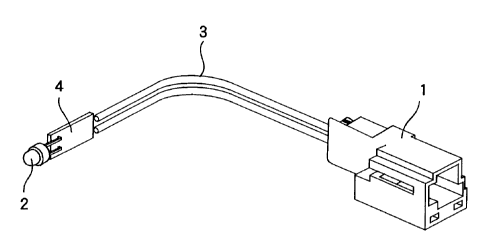
Referring now to Fig. 3 and Fig. 4, the second
embodiment will be described. In this embodiment, the
illumination lamp 2 and the connector 1 are combined as a
single unit. The same reference numerals as the first
embodiment described above designate the same members, and
the description is not made again.
In this embodiment, a part of the connector 1, the
entire printed board 4, and the illumination lamp 2 except
for the head portion are molded with a hot-melt resin in a
state in which the conductive pattern of the printed board 4
on which the illumination lamp 2 is mounted and the terminal
of the connector 1 are soldered.
CA 02364809 2001-12-11
- 7 -
In this embodiment as well, the illumination lamp
integrated with the connector 1 is obtained while preventing
the illumination lamp 2 from being melted or damaged as in
the case of the first embodiment. In addition, by mounting
the molded portion 5 to the mounted body by the use of a
projection 5a, the connector 1 can also be mounted.
Therefore, the illumination lamp 2 can receive power supply
only by connecting the male connector to the connector 1.
Since the illumination lamp constructed of a LED or a
small light bulb is molded with a hot-melt resin with a part
of the head portion of the illumination lamp exposed in the
present invention, the illumination lamp is prevented from
being melted or damaged due to the temperature of the
pressure during molding. Concurrently, since the
illumination lamp is covered by the hot-melt resin except
for the head portion, it is prevented from being damaged
even when an impact is applied thereto when it is mounted on
the mounted body or while it is in use.
Moreover, since the lead of the illumination lamp
constructed of a LED or a small light bulb is connected to
the terminal of the connector in advance, and then the
illumination lamp and a part of the connector are molded
with the hot-melt resin with a part of the illumination lamp
exposed, the connector is fixed on the mounted body simply
by mounting the illumination lamp on the mounted body,
CA 02364809 2001-12-11
- 8 -
thereby eliminating the necessity of the lead, simplifying
the mounting operation onto the mounted body, and decreasing
time and cost.