Sélection de la langue

Search

Sommaire du brevet 2364809 

Énoncé de désistement de responsabilité concernant l'information provenant de tiers

Une partie des informations de ce site Web a été fournie par des sources externes. Le gouvernement du Canada n'assume aucune responsabilité concernant la précision, l'actualité ou la fiabilité des informations fournies par les sources externes. Les utilisateurs qui désirent employer cette information devraient consulter directement la source des informations. Le contenu fourni par les sources externes n'est pas assujetti aux exigences sur les langues officielles, la protection des renseignements personnels et l'accessibilité.

Disponibilité de l'Abrégé et des Revendications

L'apparition de différences dans le texte et l'image des Revendications et de l'Abrégé dépend du moment auquel le document est publié. Les textes des Revendications et de l'Abrégé sont affichés :

  • lorsque la demande peut être examinée par le public;
  • lorsque le brevet est émis (délivrance).
(12) Brevet: (11) CA 2364809
(54) Titre français: EQUIPEMENT POUR APPAREIL D'ECLAIRAGE
(54) Titre anglais: ILLUMINATION LAMP EQUIPMENT
Statut: Durée expirée - au-delà du délai suivant l'octroi
Données bibliographiques
(51) Classification internationale des brevets (CIB):
  • F21V 99/00 (2006.01)
  • B29C 45/14 (2006.01)
(72) Inventeurs :
  • OKANO, HIROFUMI (Japon)
  • SHIMOYAMA, KEIJI (Japon)
(73) Titulaires :
  • KABUSHIKI KAISHA T AN T
(71) Demandeurs :
  • KABUSHIKI KAISHA T AN T (Japon)
(74) Agent: SMART & BIGGAR LP
(74) Co-agent:
(45) Délivré: 2007-09-04
(22) Date de dépôt: 2001-12-11
(41) Mise à la disponibilité du public: 2002-10-13
Requête d'examen: 2005-02-04
Licence disponible: S.O.
Cédé au domaine public: S.O.
(25) Langue des documents déposés: Anglais

Traité de coopération en matière de brevets (PCT): Non

(30) Données de priorité de la demande:
Numéro de la demande Pays / territoire Date
2001-114973 (Japon) 2001-04-13

Abrégés

Abrégé français

Équipement de lampe d'éclairage, dans lequel une lampe d'éclairage comprenant une DEL ou une petite ampoule électrique est moulée avec une résine thermofusible avec une partie de la portion de tête de la lampe d'éclairage exposée.


Abrégé anglais

Disclosed is illumination lamp equipment, wherein an illumination lamp comprising a LED or a small light bulb is molded with a hot-melt resin with a part of a head portion of the illuminating lamp exposed.

Revendications

Note : Les revendications sont présentées dans la langue officielle dans laquelle elles ont été soumises.


9
The embodiments of the invention in which an exclusive
property or privilege is claimed are defined as follows:
1. A method of making an illumination light assembly
comprised of a printed circuit board, and a light emitting
diode having a lead portion connected electrically to the
printed circuit board, and an illumination head portion,
said method comprising encasing both the lead portion of the
light emitting diode (LED) and the printed circuit board by
injection molding a hot melt resin material onto the lead
portion of the LED and the printed circuit board while
preventing the hot melt resin from covering the illumination
head portion of the LED such that an illumination head
portion of the LED remains visibly exposed from the
injection molded hot melt resin, wherein the hot melt resin
has an injection molding temperature in the range of 175°C.
to 225°C. and an injection molding pressure in the range of
3 to 35 Kg/cm2.
2. The method of claim 1, which further comprises
establishing electrical connection between the printed
circuit board and a connector with a lead.
3. The method of claim 2, which further comprises
establishing electrical connection directly between the
printed circuit board and a connector.

Description

Note : Les descriptions sont présentées dans la langue officielle dans laquelle elles ont été soumises.

CA 02364809 2001-12-11
- 1 -
ILLUMINATION LAMP EQUIPMENT
BACKGROUND OF THE INVENTION
1. Field of the Invention
The present invention relates to an improvement of
illumination lamp equipment to be mounted on the vehicle
illumination such as the interior lighting of the window
control switch, the interior lighting of the ashtray, and
the foot lighting, or on the front panel of the electronic
equipment, comprising a LED, a small light bulb, or the like
for indicating the operating position or the driving
condition.
2. Description of the Related Art
The conventional lighting tool used for illumination
lamp equipment described above includes LEDs or small light
bulbs. The exposed portion of the LED or the small light
bulb is made of glass or synthetic resin. Therefore, it is
difficult to mount these illumination lamps on the vehicle
or on the electronic equipment in the exposed state and it
may be broken very easily in the exposed state.
Therefore, in general, a housing for mounting the
illumination lamp such as the LED or the small light bulb is
manufactured and the illumination lamp is fitted into the
housing. However, since the housing is constructed of two

CA 02364809 2001-12-11
- 2 -
halves or formed into cylindrical shape, it is necessary to
combine two halves and secure with an adhesive agent with
the illumination lamp mounted, or to close the lid with the
illumination lamp mounted. Therefore, there is a problem in
that the point of fixation between the housing and the
illuminating lamp is susceptible to generation of a gap,
which may result in entering of dust or backlash, in
addition to the problem in that the number of components or
the number of manufacturing steps increases.
As a consequent, as a measure to solve the conventional
problems described above, molding the illumination lamp with
a nylon base synthetic resin, which is normally used for
molding, is conceivable. However, in the method of molding
the illumination lamp with nylon base resin, the temperature
of the resin is in the range of 240 to 300 C and the
injection pressure is in the range of 400 to 1300Kg/cm2 at
the time of injection as shown in Fig. 5, and thus the
illumination lamp such as the LED or the small light bulb
may be melt disadvantageously by the temperature of the
resin or may be broken by the injection pressure.
SUMMARY OF THE INVENTION
Accordingly, the present invention is intended to solve
the problems described above, and it is an object of the
present invention to provide an illumination lamp equipment

CA 02364809 2001-12-11
- 3 -
in which the illumination lamp is not melted or damaged
during injection molding by employing a hot-melt resin as a
material for molding the illumination lamp.
In order to achieve the object described above, the
illumination lamp equipment is constructed in such a manner
that the illumination lamp such as a LED or a small light
bulb is molded with a hot-melt resin with a part of the head
portion of the illuminating lamp exposed.
The lead exposed from the molded portion may be
connected to the connector, and in the case where a LED is
used as an illuminating lamp, it is also possible to connect
the lead of the LED to the printed board to which a resistor
is connected, and then mold the LED and the printed board
with the hot-melt resin except for a part of the head
portion of the LED.
Alternatively, in the case where the lead of the
illumination lamp constructed of a LED or a small light bulb
is connected to the terminal of the connector in advance,
the illumination lamp and a part of the connector are molded
with the hot-melt resin with a part of the illumination lamp
exposed, and a LED is used as an illumination lamp, it may
be constructed in such a manner that the lead of the LED is
connected to the printed board to which a resistor is
connected, and then the printed board is connected in turn
to the connector, and subsequently, the printed board, the

CA 02364809 2001-12-11
- 4 -
LED except for a part of the head portion, and a part of the
connector are molded with the hot-melt resin.
BRIEF DESCRIPTION OF THE DRAWINGS
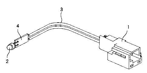
Fig. 1 is a perspective view of the illumination lamp
equipment according to the first embodiment of the present
invention showing a state before molding;
Fig. 2 is the same view as Fig. 1 showing a state after
molding;
Fig. 3 is a perspective view of the second embodiment
showing a state before molding;
Fig. 4 is the same view as Fig. 3 showing a state after
molding; and
Fig. 5 is a comparative table showing the injection
temperature and the injection pressure that vary according
to the material of molding resin.
DESCRIPTION OF THE PREFERRED EMBODIMENTS
Referring now to the drawing, an embodiment of the
illumination lamp equipment according to the present
invention will be described. Fig. 1 and Fig. 2 show the
first embodiment, in which the connector 1 to be connected
to the power supply (the connector shown in the figure is a
female connector) and the illumination lamp 2 such as a LED,
a small light bulb, or the like (the LED is shown in the

CA 02364809 2001-12-11
- 5 -
f igure) are provided separately, and the LED 2 and the
connector 1 is connected by the lead 3.
The connector 1 used here is a known type, which is
detachably mounted to the male connector (not shown) for
receiving power supply. Since the terminal of the
illumination lamp 2 is connected to the printed board 4 to
which a protective resistor (not shown) is connected, and
the printed board 4 is in turn connected to the lead 3, the
illumination lamp 2 is electrically connected to the
connector 1.
In this embodiment, the printed board 4 and the
illumination lamp 2 except for a part of the head portion
are molded by injection molding using a hot-melt resin.
Hereinafter, the portion formed by molding is referred to as
a molded portion 5.
Since the temperature of the hot-melt resin during
injection is in the range of 175 to 225 C and the injection
pressure thereof is in the range of 3 to 35Kg/cm' as is
apparent from Fig. 5, which is lower both in temperature and
pressure in comparison with the generally used synthetic
resin, even the illumination lamp 2 such as a LED, a small
light bulb, or the like that may easily be affected by heat
and pressure may be prevented from being melted by heat or
being broken by the pressure.
Since the hot-melt resin is a material that is

CA 02364809 2001-12-11
- 6 -
primarily used for adhesive agent, it exhibits superior
adhesiveness, waterproof property, dust-proof property, and
shake-proof property, molding the illumination lamp 2 with a
hot-melt resin having such characteristics may prevent
occurrence of breakdown even when it gets wet in the rain or
gathers dust, or even when it is exposed to vibration during
travel when mounted on the vehicle.
In the figure, the molded portion 5 is formed with a
projection 5a. The projection 5a is to be used as a claw
for fixing to the mounted member such as the vehicle, the
electronic equipment or the like, and the configuration
thereof may be modified depending on that of the mounting
portion of the mounted member.
Referring now to Fig. 3 and Fig. 4, the second
embodiment will be described. In this embodiment, the
illumination lamp 2 and the connector 1 are combined as a
single unit. The same reference numerals as the first
embodiment described above designate the same members, and
the description is not made again.
In this embodiment, a part of the connector 1, the
entire printed board 4, and the illumination lamp 2 except
for the head portion are molded with a hot-melt resin in a
state in which the conductive pattern of the printed board 4
on which the illumination lamp 2 is mounted and the terminal
of the connector 1 are soldered.

CA 02364809 2001-12-11
- 7 -
In this embodiment as well, the illumination lamp
integrated with the connector 1 is obtained while preventing
the illumination lamp 2 from being melted or damaged as in
the case of the first embodiment. In addition, by mounting
the molded portion 5 to the mounted body by the use of a
projection 5a, the connector 1 can also be mounted.
Therefore, the illumination lamp 2 can receive power supply
only by connecting the male connector to the connector 1.
Since the illumination lamp constructed of a LED or a
small light bulb is molded with a hot-melt resin with a part
of the head portion of the illumination lamp exposed in the
present invention, the illumination lamp is prevented from
being melted or damaged due to the temperature of the
pressure during molding. Concurrently, since the
illumination lamp is covered by the hot-melt resin except
for the head portion, it is prevented from being damaged
even when an impact is applied thereto when it is mounted on
the mounted body or while it is in use.
Moreover, since the lead of the illumination lamp
constructed of a LED or a small light bulb is connected to
the terminal of the connector in advance, and then the
illumination lamp and a part of the connector are molded
with the hot-melt resin with a part of the illumination lamp
exposed, the connector is fixed on the mounted body simply
by mounting the illumination lamp on the mounted body,

CA 02364809 2001-12-11
- 8 -
thereby eliminating the necessity of the lead, simplifying
the mounting operation onto the mounted body, and decreasing
time and cost.

Dessin représentatif
Une figure unique qui représente un dessin illustrant l'invention.
États administratifs

2024-08-01 : Dans le cadre de la transition vers les Brevets de nouvelle génération (BNG), la base de données sur les brevets canadiens (BDBC) contient désormais un Historique d'événement plus détaillé, qui reproduit le Journal des événements de notre nouvelle solution interne.

Veuillez noter que les événements débutant par « Inactive : » se réfèrent à des événements qui ne sont plus utilisés dans notre nouvelle solution interne.

Pour une meilleure compréhension de l'état de la demande ou brevet qui figure sur cette page, la rubrique Mise en garde , et les descriptions de Brevet , Historique d'événement , Taxes périodiques et Historique des paiements devraient être consultées.

Historique d'événement

Description Date
Inactive : Périmé (brevet - nouvelle loi) 2021-12-13
Représentant commun nommé 2019-10-30
Exigences relatives à la nomination d'un agent - jugée conforme 2015-09-11
Inactive : Lettre officielle 2015-09-11
Exigences relatives à la révocation de la nomination d'un agent - jugée conforme 2015-09-11
Demande visant la nomination d'un agent 2015-08-20
Demande visant la révocation de la nomination d'un agent 2015-08-20
Accordé par délivrance 2007-09-04
Inactive : Page couverture publiée 2007-09-03
Préoctroi 2007-06-21
Inactive : Taxe finale reçue 2007-06-21
Un avis d'acceptation est envoyé 2007-04-03
Lettre envoyée 2007-04-03
Un avis d'acceptation est envoyé 2007-04-03
Inactive : CIB enlevée 2007-03-29
Inactive : CIB attribuée 2007-03-29
Inactive : CIB en 1re position 2007-03-29
Inactive : CIB enlevée 2007-03-29
Inactive : Approuvée aux fins d'acceptation (AFA) 2007-03-21
Inactive : CIB de MCD 2006-03-12
Lettre envoyée 2005-02-15
Modification reçue - modification volontaire 2005-02-04
Exigences pour une requête d'examen - jugée conforme 2005-02-04
Toutes les exigences pour l'examen - jugée conforme 2005-02-04
Requête d'examen reçue 2005-02-04
Demande publiée (accessible au public) 2002-10-13
Inactive : Page couverture publiée 2002-10-13
Inactive : CIB en 1re position 2002-02-14
Inactive : Certificat de dépôt - Sans RE (Anglais) 2002-01-15
Lettre envoyée 2002-01-15
Demande reçue - nationale ordinaire 2002-01-15

Historique d'abandonnement

Il n'y a pas d'historique d'abandonnement

Taxes périodiques

Le dernier paiement a été reçu le 2006-12-05

Avis : Si le paiement en totalité n'a pas été reçu au plus tard à la date indiquée, une taxe supplémentaire peut être imposée, soit une des taxes suivantes :

  • taxe de rétablissement ;
  • taxe pour paiement en souffrance ; ou
  • taxe additionnelle pour le renversement d'une péremption réputée.

Les taxes sur les brevets sont ajustées au 1er janvier de chaque année. Les montants ci-dessus sont les montants actuels s'ils sont reçus au plus tard le 31 décembre de l'année en cours.
Veuillez vous référer à la page web des taxes sur les brevets de l'OPIC pour voir tous les montants actuels des taxes.

Titulaires au dossier

Les titulaires actuels et antérieures au dossier sont affichés en ordre alphabétique.

Titulaires actuels au dossier
KABUSHIKI KAISHA T AN T
Titulaires antérieures au dossier
HIROFUMI OKANO
KEIJI SHIMOYAMA
Les propriétaires antérieurs qui ne figurent pas dans la liste des « Propriétaires au dossier » apparaîtront dans d'autres documents au dossier.
Documents

Pour visionner les fichiers sélectionnés, entrer le code reCAPTCHA :


Pour visualiser une image, cliquer sur un lien dans la colonne description du document. Pour télécharger l'image (les images), cliquer l'une ou plusieurs cases à cocher dans la première colonne et ensuite cliquer sur le bouton "Télécharger sélection en format PDF (archive Zip)" ou le bouton "Télécharger sélection (en un fichier PDF fusionné)".

Liste des documents de brevet publiés et non publiés sur la BDBC .

Si vous avez des difficultés à accéder au contenu, veuillez communiquer avec le Centre de services à la clientèle au 1-866-997-1936, ou envoyer un courriel au Centre de service à la clientèle de l'OPIC.


Description du
Document 
Date
(aaaa-mm-jj) 
Nombre de pages   Taille de l'image (Ko) 
Dessin représentatif 2002-02-17 1 7
Revendications 2001-12-10 2 40
Description 2001-12-10 8 269
Abrégé 2001-12-10 1 8
Dessins 2001-12-10 3 62
Revendications 2005-02-03 1 31
Dessin représentatif 2007-08-08 1 7
Courtoisie - Certificat d'enregistrement (document(s) connexe(s)) 2002-01-14 1 113
Certificat de dépôt (anglais) 2002-01-14 1 164
Rappel de taxe de maintien due 2003-08-11 1 106
Accusé de réception de la requête d'examen 2005-02-14 1 176
Avis du commissaire - Demande jugée acceptable 2007-04-02 1 161
Correspondance 2007-06-20 1 29
Correspondance 2015-08-19 3 90
Correspondance 2015-09-10 1 22
Correspondance 2015-09-10 1 25