Language selection

Search

Patent 2374427 Summary

Third-party information liability

Some of the information on this Web page has been provided by external sources. The Government of Canada is not responsible for the accuracy, reliability or currency of the information supplied by external sources. Users wishing to rely upon this information should consult directly with the source of the information. Content provided by external sources is not subject to official languages, privacy and accessibility requirements.

Claims and Abstract availability

Any discrepancies in the text and image of the Claims and Abstract are due to differing posting times. Text of the Claims and Abstract are posted:

  • At the time the application is open to public inspection;
  • At the time of issue of the patent (grant).
(12) Patent: (11) CA 2374427
(54) English Title: SELF-PUNCHING FASTENER
(54) French Title: DISPOSITIF DE FIXATION POUR AUTOPERCAGE
Status: Expired
Bibliographic Data
(51) International Patent Classification (IPC):
  • F16B 37/00 (2006.01)
  • B23P 19/06 (2006.01)
  • F16B 37/06 (2006.01)
(72) Inventors :
  • ROSS, GEROLD (Germany)
  • LUDWIG, DETLEF (Germany)
(73) Owners :
  • NEDSCHROEF SCHROZBERG GMBH (Germany)
(71) Applicants :
  • TEXTRON VERBINDUNGSTECHNIK GMBH & CO. OHG (Germany)
(74) Agent: KIRBY EADES GALE BAKER
(74) Associate agent:
(45) Issued: 2010-11-30
(22) Filed Date: 2002-03-04
(41) Open to Public Inspection: 2003-02-22
Examination requested: 2006-04-10
Availability of licence: N/A
(25) Language of filing: English

Patent Cooperation Treaty (PCT): No

(30) Application Priority Data:
Application No. Country/Territory Date
201 13 853.0 Germany 2001-08-22

Abstracts

English Abstract


A self-punching fastener can be pressed into a metal
sheet member in a way that prevents against rotation and
pressing out. The fastener has an annular body with a
side facing the metal sheet having radially disposed
projections. The projections are pressed into the metal
sheet member during the pressing-in and thereby secures
the fastener against rotation. An interior thread is
positioned in the center of fastener. An annular
depression is provided on the side of the annular body
facing the metal sheet member. Material is displaced
into the annular depression during the setting.


French Abstract

Attache auto-emboutissante à enfoncer dans un élément de feuille métallique de façon à empêcher la rotation ou le détachement. L'attache est constituée d'un corps annulaire dont l'un des côtés fait face à la feuille métallique et comporte des projections disposées en rayons. Les projections s'enfoncent dans la feuille métallique pendant l'emboutissage de façon à arrimer l'attache. Le centre de l'attache est fileté à l'intérieur. Le côté du corps annulaire comprend une cavité annulaire faisant face à la feuille métallique. Une partie du matériau est poussée dans la cavité annulaire pendant l'opération.

Claims

Note: Claims are shown in the official language in which they were submitted.


6

CLAIMS


1. Self-punching fastener for pressing into a metal
sheet in a manner that is safe from rotation and
pressing-out, the fastener comprising:

an annular body, having radially positioned
projections on a side thereof facing the metal sheet, the
projections being pressed into the metal sheet during
pressing and thereby securing the fastener against
rotation;

an interior thread in a center of the annular body;
and
the annular body having an annular depression on the
side facing the metal sheet, the projections being evenly
distributed in the annular depression;
the depression having a punching collar at an inner
limitation and a collar at an exterior limitation, the
projections being positioned at the collar at the
exterior limitation, the collar at the exterior
limitation having an undercut facing the annular
depression to receive material of the metal sheet for
locking against an axial pressing-out;
the punching collar limiting the annular depression
on the side of the annular body facing the metal sheet in
the direction of the interior thread such that the
punching collar punches a hole of a diameter of the
punching collar into the metal sheet during setting of
the fastener, the punching collar having an undercut
facing the annular depression in which material from the
metal sheet is received during pressing-in to provide a
further locking of the fastener against an axial
pressing-out, the annular depression being free of
projections adjacent the punching collar.


7

2. The fastener according to claim 1, wherein the
punching collar is adapted to a gauge of the metal sheet
with respect to a height of the metal sheet.


3. The fastener according to any one of the claims 1
or 2, wherein a bottom face of the annular depression is
inclined from an interior to an exterior in a direction
of the metal sheet.

Description

Note: Descriptions are shown in the official language in which they were submitted.


CA 02374427 2009-06-02

1
SELF-PUNCHING FASTENER
FIELD OF THE INVENTION

The present invention relates to a self-punching fastener
for pressing into a metal sheet in a manner that is safe
from rotation and pressing out.

BACKGROUND OF THE INVENTION

It is the task of the present invention to improve a
fastener so that a maximal range of gauges of the metal
sheet can be used without changing geometry of the

fastener and still providing a high safety against
rotation and pressing out without requiring a previous
punching or a special preparation of the holes into which
the fastener is to be set.

According to the prior art, known solutions were based on
the assumption that an optimal safety against rotation
and pressing out and a broad range of use of the fastener
is achieved if continuous ridges are provided within the
annular depression for locking against rotation and the
bottom of the annular depression is parallel to the
surface of the metal sheets.


CA 02374427 2009-06-02

2
SUMMARY OF THE INVENTION

The present invention is based on achieving an optimal
safety against rotation using burl-shaped locking
elements in a maximal distance to a central axis to make

use of the most effective lever against the rotational
momentum at the utmost supporting collar of an annular
depression.

By the above described displacing of the security against
rotation and the inclined formation of the bottom of the
annular depression at the innermost limit of the annular
depression - the punching collar - there is more space
available for the penetration of the cutting ring of the
punching die. This means it is possible to work with
larger thicknesses of the metal sheets or larger gauge

ranges with the solution according to the invention.
The coordination between the punching die geometry and
the shape of the annular depression and the security
against rotation according to the invention ensures that,
after the pressing-in of the metal sheet, jamming on the

punching die is prevented providing a high working
safety.

Material from the metal sheet is shaped into undercuts
formed during the production of parts and at the inner
punching collar as on the supporting collar of the

annular depression during the pressing-in. This ensures
that even when working with thin metal sheets, a high
safety against rotation and pressing out of the fastener
is achieved.


CA 02374427 2009-06-02

3
The shape of the projections or burls can be arched as
well as with sharp edges (triangular).

BRIEF DESCRIPTION OF THE DRAWINGS

In the following, the invention is more detailly
described with reference to the attached drawings.

Fig. 1 is a side elevation view of a fastener according
to the present invention;

Fig. 2 is a bottom plan view of the fastener of Fig. 1;
Fig. 3 is a bottom plan view of another embodiment of the
fastener;

Fig. 4 is a side elevation view of the fastener of Fig. 1
and a punching die in an open configuration;

Fig. 5 is a side elevation view of the fastener of Fig. 1
and the punching die in a closed configuration; and

Fig. 6 is a side elevation view of the fastener of Fig. 1
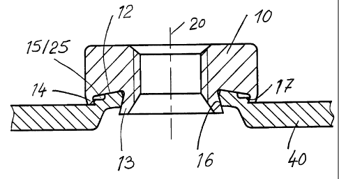
set in a metal sheet member.

DETAILED DESCRIPTION

Fig. 1 shows a fastener according to the invention in the
shape of a nut consisting of an annular basic body 10.

In a center of the cylindrical fastener 10 there is a
throughbore on which is formed a thread 11 over at least
a part of the height of the fastener 10.


CA 02374427 2009-06-02

4
On the bottom side, the fastener 10 has an annular
depression 12. The bottom face of the annular
depression 12 starts from an inner limitation, the
punching collar 13 and is inclined to an outer

limitation, the supporting collar 14. Within this
annular depression 12 there are evenly distributed
burl-shaped locking elements 15 in an annular array at
the supporting collar 14. The punching collar 13 has an
undercut 16 towards an axis 20 of the fastener 10. The
supporting collar 14 has an undercut 17 in the direction
of an exterior enveloping face 18 of the fastener 10.
The punching collar 13 has a cutting edge 19.

Fig. 2 shows the fastener 10 of Fig. 1 in a bottom view.
The shape and the position of the burl-shaped locking
elements 15 are clearly shown. The burl-shaped locking

elements 15 are positioned at the outer supporting
collar 14 and form a free-space towards the punching
collar 13. In this representation (Fig. 2) the variant
with annularly shaped burl-shaped locking elements 15 is
shown.

Fig. 3 shows the fastener 10 in an embodiment having
sharp-edge (triangular) burl-shaped locking elements 25.
Fig. 4 shows the fastener 10 in accordance to Figs. 1, 2
and 3 as well as a punching die 30 and a metal sheet 40.
From this representation it can be seen that the metal
sheet 40 does not have a prefabricated hole and does not
need any further preparation. The punching die 30 has a
cutting edge 31 and a swaging ring 32 having a special
geometry 33. An exterior enveloping face 34 of the
swaging ring 32 runs conically towards the central


CA 02374427 2009-06-02

axis 20 of the punching die 30. This ensures that after
the punching and pressing-in of the metal sheet 40 into
the annular depression 12, jamming of the swaging ring 32
in the metal sheet 40 is avoided.

5 Fig. 5 shows the fastener 10 of Figs. 1 to 3 shortly
after the finalization of the setting procedure. The
punching collar 13, in cooperation with the cutting edge
31 of

the punching die 30, punches a disk 41 from the metal
sheet 40. The material of the metal sheet 40 is swaged
into the annular depression 12 by the swaging ring 32
enclosing the burl-shaped locking elements 15, 25. The
stemmed out disk 41 is discarded downwardly from the
punching die 30.

Fig. 6 shows the fastener 10 completely set in a metal
sheet 40. The action of the undercut 16, 17 at the
punching collar 13 and at the supporting collar 14 is
clearly shown. The annular depression 12 is filled with
the material of the metal sheet 40. The burl-shaped
locking elements 14, 25 are embedded in the metal
sheet 40. The positive action of the bottom face of the
annular depression 12 inclined to the exterior for
enlarging the active length of the punching collar 13 and
therefore for increasing the range of useable gauge

ranges of the metal sheets for the fastener 10 according
to the invention can be clearly noticed.

Representative Drawing
A single figure which represents the drawing illustrating the invention.
Administrative Status

For a clearer understanding of the status of the application/patent presented on this page, the site Disclaimer , as well as the definitions for Patent , Administrative Status , Maintenance Fee  and Payment History  should be consulted.

Administrative Status

Title Date
Forecasted Issue Date 2010-11-30
(22) Filed 2002-03-04
(41) Open to Public Inspection 2003-02-22
Examination Requested 2006-04-10
(45) Issued 2010-11-30
Expired 2022-03-04

Abandonment History

There is no abandonment history.

Payment History

Fee Type Anniversary Year Due Date Amount Paid Paid Date
Registration of a document - section 124 $100.00 2002-03-04
Application Fee $300.00 2002-03-04
Maintenance Fee - Application - New Act 2 2004-03-04 $100.00 2004-02-18
Maintenance Fee - Application - New Act 3 2005-03-04 $100.00 2005-02-18
Maintenance Fee - Application - New Act 4 2006-03-06 $100.00 2006-01-31
Request for Examination $800.00 2006-04-10
Maintenance Fee - Application - New Act 5 2007-03-05 $200.00 2007-01-31
Maintenance Fee - Application - New Act 6 2008-03-04 $200.00 2008-02-05
Registration of a document - section 124 $100.00 2008-05-26
Maintenance Fee - Application - New Act 7 2009-03-04 $200.00 2009-02-04
Maintenance Fee - Application - New Act 8 2010-03-04 $200.00 2010-02-16
Final Fee $300.00 2010-09-15
Maintenance Fee - Patent - New Act 9 2011-03-04 $200.00 2011-01-19
Maintenance Fee - Patent - New Act 10 2012-03-05 $450.00 2012-03-29
Maintenance Fee - Patent - New Act 11 2013-03-04 $250.00 2013-01-28
Maintenance Fee - Patent - New Act 12 2014-03-04 $450.00 2014-07-10
Maintenance Fee - Patent - New Act 13 2015-03-04 $450.00 2016-02-25
Maintenance Fee - Patent - New Act 14 2016-03-04 $250.00 2016-02-25
Maintenance Fee - Patent - New Act 15 2017-03-06 $450.00 2017-01-25
Registration of a document - section 124 $100.00 2017-07-28
Maintenance Fee - Patent - New Act 16 2018-03-05 $650.00 2018-03-22
Maintenance Fee - Patent - New Act 17 2019-03-04 $650.00 2019-03-20
Maintenance Fee - Patent - New Act 18 2020-03-04 $450.00 2020-02-20
Owners on Record

Note: Records showing the ownership history in alphabetical order.

Current Owners on Record
NEDSCHROEF SCHROZBERG GMBH
Past Owners on Record
ACUMENT GMBH & CO. OHG
LUDWIG, DETLEF
ROSS, GEROLD
RT HOLDINGS III WG (US), LP SCS
RUIA GLOBAL FASTENERS AG
TEXTRON VERBINDUNGSTECHNIK GMBH & CO. OHG
WHITESELL GERMANY GMBH & CO. KG
Past Owners that do not appear in the "Owners on Record" listing will appear in other documentation within the application.
Documents

To view selected files, please enter reCAPTCHA code :


To view images, click a link in the Document Description column. To download the documents, select one or more checkboxes in the first column and then click the "Download Selected in PDF format (Zip Archive)" or the "Download Selected as Single PDF" button.

List of published and non-published patent-specific documents on the CPD .

If you have any difficulty accessing content, you can call the Client Service Centre at 1-866-997-1936 or send them an e-mail at CIPO Client Service Centre.


Document
Description 
Date
(yyyy-mm-dd) 
Number of pages   Size of Image (KB) 
Description 2002-03-04 4 182
Claims 2002-03-04 2 63
Description 2009-06-02 5 157
Abstract 2009-06-02 1 16
Claims 2009-06-02 2 46
Drawings 2002-03-04 3 63
Representative Drawing 2002-06-03 1 8
Cover Page 2003-01-27 1 39
Abstract 2002-03-04 1 20
Cover Page 2010-11-08 1 37
Claims 2010-04-14 2 48
Representative Drawing 2010-11-08 1 9
Prosecution-Amendment 2006-04-10 1 33
Assignment 2002-03-04 4 127
Correspondence 2010-09-15 1 36
Assignment 2008-05-26 6 208
Assignment 2008-09-17 8 224
Prosecution-Amendment 2009-03-17 4 154
Prosecution-Amendment 2009-06-02 11 306
Prosecution-Amendment 2009-11-18 2 52
Prosecution-Amendment 2010-04-14 4 107
Fees 2012-03-29 1 163
Correspondence 2012-03-29 1 89
Fees 2014-07-10 1 33
Fees 2016-02-25 1 33